Quadrupedal Mechanics - Anatomy & Physiology
Introduction
Anatomy should be studied using mechanical principles
It is debatable whether the mysteries of life can be interpreted entirely by physical laws, but it is unquestionably true that life cannot be understood without reference to these laws. Thus we cannot interpret, for instance, the nature of an injury to the suspensory ligament of a horse, or the symptoms of a congenital abnormality of the hip of a dog, unless we understand the reason for the particular design of these structures in the normal living animal. The description of structure alone, as encountered in most textbooks of veterinary anatomy, is less interesting and more difficult to learn. Crushed under a load of facts, the student quickly discovers there is no incentive to reason for her or himself.
By applying mechanical principles to the musculoskeletal system of quadrupeds, this book attempts to explain the complexities of body structure. Hopefully, the reader will also gain a greater appreciation of the beauty of animal form and function. Of course, the ideas expressed here are not the last word on the subject. If argument is provoked, this book will be serving its purpose all the more.
The animal machine
A machine is a device for applying forces; an animal is therefore a machine. Force is developed in an animal's muscles, and is transmitted to its site of application by the supporting tissues composed of bone, cartilage, tendon and ligament. These tissues together form the musculoskeletal system.
The animal machine has some remarkable properties not found in man-made machines. Try to envision something man-made that grows without interruption to function, that if damaged or fatigued it can repair itself by replacement of component parts, frequently with little impairment to function, that can adjust in response to demand, such as adaptation to exercise, and that is constructed to last literally a life time. As well, the animal machine can also be a source of pleasure to those who participate in or view athletic performances. And last, we usually take it for granted that the animal machine should contribute in no small way to world agriculture, trade and nutrition: some parts of this machine are good to eat.
No matter how you view it, this book deals with an extraordinary machine.
Elasticity: external forces and stored energy
What this machine is made of: passive and active tissues
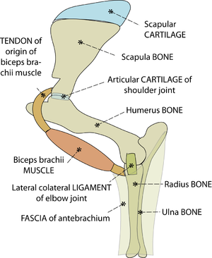
The tissues of the musculoskeletal system are bone, cartilage, ligament, tendon, fascia and muscle (Fig. 2.1). The non-muscular parts support the body passively by resisting forces that are applied to the body from outside (extrinsic) or those that are created intrinsically within the body. The most significant extrinsic forces are the earth's gravitational force on the mass of the animal, and the reaction of the ground. An animal, once it is born, must spend most of its life battling with gravity and the problems of contact with ground surfaces.
Animals also derive support from the activity of their muscles, as evidenced from the inability of an anesthetised animal to stand. This active type of support will be discussed in Sections 4 and 5.
- Fig. 2.1 Tissues of the musculoskeletal system
- This is a stylised view of the lateral aspect of the proximal left forelimb of the sheep. The skeleton is made of bones and cartilages. A combination of ligaments, muscles & tendons, and sheets of fascia, examples of which are shown, hold these together. Without these soft tissues around them, the jointed bones will not support the weight of the sheep.
The elasticity of tissues
An appreciation of the concept of elasticity is essential to understanding the mechanics of animals.
All materials are elastic to a lesser or a greater extent, even tissues like bone that seem to be stiff rather than elastic. The stiffness is only relative. After being deformed by an external force, all tissues must return to their original shape. If they did not, the body would be permanently deformed. Elasticity is a special function of the passive musculoskeletal tissues.
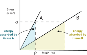
Elasticity is measured by determining the effect of stress, defined as force per unit area, on the shape of the material. When this stress acts in only one direction, this shape change is measured as strain, the distortion per original unit distance, expressed as a percentage.
At a particular percentage of strain, ρ, a stiffer material will store more elastic energy than a more elastic tissue. Suppose that at this strain percentage, the material can no longer be deformed without damage. Fracture will occur, and because the stiffer material releases more energy it will shatter rather that suffering a simple break. Bone fractures are discussed later in Chapter 3.
- Fig. 2.2 Stress, strain & elastic energy
- Two linearly elastic tissues A and B have stress - strain curves as shown. At any given value of stress, ρ, the energy absorbed by A, represented here by the area beneath the curve, is less than that absorbed by B. A is stiffer than B. If A and B were bones, A would be the more mineralised.
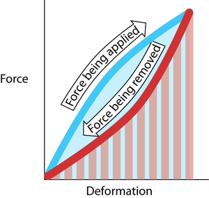
When an elastic material is strained, work is done on it and energy is stored in it. Elastic energy is a form of potential energy. A rubber ball falling on to a hard surface converts what was previously kinetic energy into elastic energy on impact. This elastic energy is released again as kinetic energy when the ball bounces. The ball does not, however, attain the same height as previously. The elastic framework of an animal’s body behaves similarly, as it bounces up and down during running (Fig. 2.4). Some of the kinetic energy is lost as heat. The less energy lost in this way, the greater the elastic resilience of the material. Resilience is the work recovered from a material in elastic recoil, expressed as a percentage of the work previously done in straining it (Fig. 2.5). Passive musculoskeletal tissues should be as resilient as possible, to conserve energy.
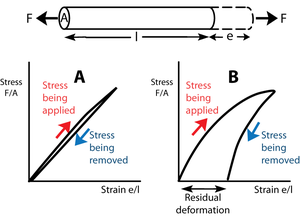
- Fig. 2.3 Elasticity
- The force F tenses a block of material of transverse sectional area A and length l, producing a deformation e. In Figure 2.3A, stress is proportional to strain. The slope of this line is the elastic modulus.
- Upon removal of the stress, the block returns to its original shape. The block is perfectly elastic. In Figure 2.3B, the elastic modulus is not constant; with more stress, a disproportionate deformation is produced.
- For this reason, and also because when the stress is removed some of the deformation remains, the block in this instance is imperfectly elastic. Such a residual deformation is not useful in animal mechanics.
Elastic resilience
When an elastic material is strained, work is done on it and energy is stored in it. Elastic energy is a form of potential energy. A rubber ball falling on to a hard surface converts what was previously kinetic energy into elastic energy on impact. This elastic energy is released again as kinetic energy when the ball bounces. The ball does not, however, attain the same height as previously. The elastic framework of an animal’s body behaves similarly, as it bounces up and down during running (Fig. 2.4). Some of the kinetic energy is lost as heat. The less energy lost in this way, the greater the elastic resilience of the material. Resilience is the work recovered from a material in elastic recoil, expressed as a percentage of the work previously done in straining it (Fig. 2.5). Passive musculoskeletal tissues should be as resilient as possible, to conserve energy.
- Fig. 2.4 Elastic resilience
- The work done in deforming the material is Fd, the product of force and distance. This is the area under the curve made during the application of the force (blue). The work done by the elastic restoring force is the area under the curve made during the removal of the deforming force (red hatching). In this example, these two areas are not the same. The difference in area is the energy lost as heat. The resilience is the red hatched area as a percentage of the blue area.
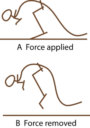
- Fig. 2.5 A hopping kangaroo
- Compare the angle of the hock joint when the limb bears weight, and when not weight-bearing. The passive tissues supporting this joint store energy in A and release it in B. At hopping speeds of between 10 and 35 km/h, kangaroo locomotion is remarkably efficient. This is due to the almost 100% resilience of the elastic support of the hock joint.
What makes materials elastic?
The elasticity of materials comes about in several different ways:
Molecular elasticity: Stress may produce a molecular change. The keratinous structures of mammals (hair, wool, hooves and horns) are elastic because the keratin molecule changes from a tight helix to an extended form when it is stretched.
Crystalline elasticity: Stress on a material such as steel results in changes in distances between atoms. A large stress produces only a small distortion. The elasticity is therefore low.
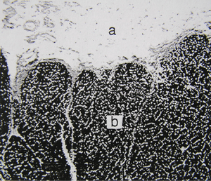
Rubbery elasticity: The elasticity of the most elastic materials results from the cross-linking of long, flexible, convoluted polymers. In rubber, these cross-links are formed by sulphur during the process of vulcanisation. Distortion of a block of rubber results in a distortion of each molecule, which is restored when the stress is removed. Cross-linking is necessary to prevent the molecules from slipping past each other. Elasticity of rubber is lost when there are too many cross-links or when the temperature is too low. Several biological materials show rubbery elasticity. In vertebrates, elastin is present in thin strands in loose connective tissue, providing the extreme elasticity of such tissues as the dermis. It predominates in the middle coat of the wall of large arteries and in the nuchal ligament of herbivores (Figs. 2.6, 2.7). It is not fibrous, but consists of thin homogeneous strands. Its elasticity is similar to that of lightly vulcanised rubber.
- Fig. 2.6 Elastin in the nuchal ligament of a sheep
- a. Loose connective tissues surrounding the ligament.
- b. Elastin fibres, stained with Verhoeff’s hematoxylin, in the ligament.
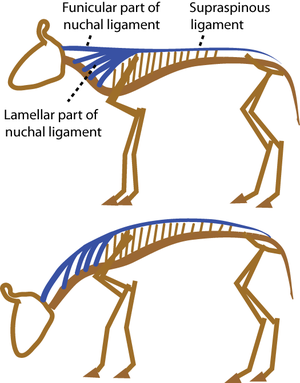
- Fig.2.7 A grazing cow.
- Herbivores have heavy heads held at the end of a long neck. As they flex their neck to graze, the nuchal ligament is strained by 50%. The elastic energy stored is released as the head is raised, so that little muscular effort is needed. A spring loaded garage door borrows this principle from the cow.
Fibrous elasticity: Polymeric molecules derive their elasticity by being arranged partly in ordered patterns to form crystalline regions, and partly with a random arrangement in amorphous regions. Examples of elastic materials of this kind include synthetic textiles like nylon and polyester, and natural ones like silk. Collagen, the main component of the passive musculoskeletal system, also has polymeric molecules, with the crystalline part composed of aligned and cross-linked molecules, appearing as fibrils (Figs. 2.8, 2.9). The molecules are aligned in a specific direction to form fibrils.
The significance of collagen'
The fibrous elastomer collagen is by far the most predominant passive supporting substance in vertebrates. 20% of the protein of a mouse is collagen. Tendon, ligament and dermis are almost pure collagen, and it is a major constituent of bone and fibrocartilage. Few tissues lack it entirely. Collagen quality is of commercial interest because it determines the tenderness and appropriate cooking methods of different muscles, at different stages of growth.
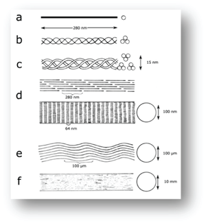
- Fig. 2.8 Molecular structure of collagen in a tendon, diagrammatic
- Tendon structure as envisaged by:
- a., protein chemistry;
- b., c., and d., X-ray diffraction;
- d., electron microscopy;
- e., light microscopy and
- f., as seen grossly in a large animal.
Collagen molecules, fibrils and fibres
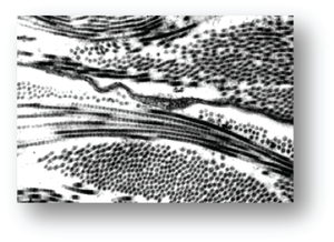
Collagen fibrils are formed when three tropocollagen molecules, each consisting of three helically arranged polypeptide chains 280 nm long, coil helically together, and align with other such "super helices". These polymeric molecules each overlap about one quarter of their length, so that an axial periodicity of 60-70 nm is visible with the electron microscope (Fig. 2.9). A collagen fibre is formed from bundles of fibrils (Fig. 2.8). Single collagen fibres are visible with the light microscope in connective tissues. They accumulate in bundles or sheets to form the gross structures ligaments, tendons and fasciae.
- Fig. 2.9 Collagen structure, viewed electron-microscopically
- Magnification x25,000.
- Lateral accessoriometacarpal ligament of a horse.
- Collagen fibrils, sectioned longitudinally and transversely (from Deane, Massey thesis, 1991).
Collagen matures with age
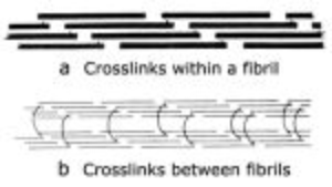
Stable aggregations of collagen molecules to form fibrils are achieved by cross-linking of the molecules. These give collagen both strength and elasticity. In newly formed collagen, the cross-links are relatively few, but with age, there is a significant increase in the number and the stability of the cross-links. This has two significant effects. Excessive stress on immature collagen contributes to tendon and ligament disease in young animals; the training of horses especially must take the aging of collagen into account. Also, variations in collagen cross-links cause the toughness associated with different cuts of meat, and with the increase in toughness in meat from older animals.
- Fig. 2.10 Collagen cross-links
- Crosslinks in immature connective tissue pass between collagen molecules within a fibril (a). The molecules are linked head to tail to form an infinite polymer.
- In a mature collagen fibre, (b), the crosslinks pass between the fibrils to link them in register.
- (Adapted from Bailey, 1988).
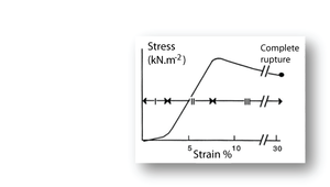
- Fig. 11 Tensile stress in collagen
- The stress–strain relationship in a bundle of collagen fibres, at a low rate of strain.
- Phase I: Rapid elongation as the "crimp" in the collagen fibres is eliminated. This part of the curve is smaller at the high strain rates likely to occur in vivo.
- Phase II: Stress is proportional to strain. This elastic phase of collagen is the phase most useful in vivo.
- Phase III: Breakdown of the crystalline components of the collagen fibres. Deformation takes place with progressively less stress.
Putting the stress on to collagen
When a collagenous structure, such as tendon, progressively undergoes tensile stress in a laboratory preparation, three stages o stress strain relationships are recognised (Fig. 2.11). During the first stage, the wavy pattern or crimp seen in bundles of fibres is removed. This crimp is probably due to an in–series elastic component, accounting for the high elasticity over this stage. This first stage is less apparent when the strain rate is high. Such a high strain rate is the likely situation in tendon in vivo. The second stage is the true elastic stage for collagen fibres. With stretch, the axial periodicity of the fibres is increased. The elasticity of collagen is about one three hundredth that of elastin. This makes it a suitable material for structures that must withstand large forces without stretching too much. In stage three, there is a loss of elasticity. The crosslinks between the fibrils have been broken by the stress and the material exhibits viscous flow. The strain remains after removal of the stress, defined as residual deformation in Fig 2.3.
Organisation of collagen in bone and fibrocartilage
In both bone and fibrocartilage, collagen fibrils are embedded in a matrix. For bone, the matrix is made of mineral crystals and for cartilage the matrix is mucopolysaccaride. Bone and fibrocartilage are therefore both heterogeneous. Each is a composite material consisting of several different components. In bone, collagen forms one third of the weight and one half of the volume of the tissue. The arrangement of the collagen determines the quality of the bone. In the most structured bone, the collagen fibres are arranged parallel to one another in sheets, or lamellae, 5µm thick (Fig. 2.12). The alignment of the collagen alternates between the lamellae. In some bones, the lamellae form concentric rings around blood vessels. Each set of such rings is called an osteone. Not all bone is, however, lamellar bone; such highly organised bone is only common in larger reptiles and mammals. The predominant component of bone, by weight, is the organic part. Crystals of hydroxyapatite that lie between the collagen fibrils within each lamella form this. The resulting mineralised tissue is one twentieth as elastic as pure collagen in tension. Fibrocartilage contains collagen in a less organised pattern than lamellar bone. The more elastic type of cartilage contains elastin also. The matrix of cartilage is a polymer made up of proteins and polysaccharides in hydrated complexes, known as mucopolysaccharide.
- Fig. 2.12 Bone structure
- A magnified, schematic view of a section from the shaft of a bovine femur.
- a periosteum
- b lamellar bone
- c osteone
- d vascular canal
The advantage and organisation of composite materials
As examples of composite materials, the physical properties of bone and fibrocartilage are unlike those of either component taken alone, and are not the sum of the two taken together. Collagen fibres resist tension forces and hydroxyapatite resists compression forces. The composites, bone and fibrocartilage may therefore be likened to manmade materials such as ferroconcrete, fibreglass or filled rubber. The discovery of these revolutionised construction of bridges, boats and tyres, as was animal construction revolutionised when bony skeletons were invented much longer ago. Structures made up of bone or fibro-cartilage are seldom homogeneously constituted. Their composite materials have specific orientations and densities, resulting in compact or spongy bone, or hyaline cartilage with little collagen or dense fibrocartilage. The elasticities and strengths of these depend on both the orientation of the force to the direction of the fibrous component, or "grain", and the proportions of each component. For instance, bone lamellae are densest around the surface and along the shaft of a bone (Fig. 2.13). The reasons for this are apparent once the forces within the structure are considered.
- Fig. 2.13 Structure of a long bone
- The architectural requirements specify that only sufficient material should be used to allow for stresses the bone is expected to tolerate. Thus, the extremities are composed of spongy bone internally, the shaft is osseous only on the outside, and the dense laminar bone of the shaft is thickest halfway along its length. During growth, an increase in the length of the bone occurs by ossification of cartilage, produced from the epiphyseal line, in the metaphyseal region. This growth is minimally affected by stresses in tendons and ligaments, because these structures are attached to the epiphyseal regions beyond the epiphyseal lines.
Compression and tensile strength of bone and cartilage
The strength of a tissue is determined by measuring the minimum stress needed to produce permanent deformity in the material. Deformation comes about by pairs of opposing forces that cause compression, tension or shear (Fig 2.14). The compressive strength of fresh compact bone loaded parallel to the grain is about 170 MN.m-2. This is impressive, considering that the compressive strength of marble and granite is little more, at 200MN.m-2. Cartilage has a compressive strength lower than bone.
• Fresh, compact bone loaded parallel to the grain has a tensile strength of 80MN.m-2. For steel it is 500MN.m-2. Again, cartilage has a compressive strength lower than bone.
• The resistance of compact bone to shear may be as low as 50MN.m-2 if stressed parallel to the grain, and as high as 120 MN.m-2 if stressed transversely to the grain. Cartilage, tendon and ligament have less resistance to shear.
If bone is mechanically superior to other materials, why is it not used more often for preference?
- Fig. 2.14 Types of stress
- Pairs of forces can exert three types of stress on solids
Weight economy and the choice of building materials
In nature, the most successful animal would be expected to economise on the use of building materials. Living in a highly competitive athletic environment, neither the hunter of the hunted can afford the luxury of excessive inertia-producing mass. Wild animals are lean and mean. The successful animal will employ in any given situation the least dense material for the task, in relation to the maximal mechanical demands that are made. With regard to weight economy, therefore, the specifications of the animal machine will use bones where high compression and shear forces are to be resisted, cartilage where these forces are lower and where lightness and elasticity are required, and pure collagen fibres where tensile forces alone are to be resisted. Because animals economise on materials, the size and shape of their various parts indicate to us much about their function. Since its establishment as the first modern science by Vesalius in 1543, anatomy has depended very much on this principle.
Grace and coordination: the significance of strain rate
In locomotion, and when the animal must absorb accidental impact, dynamic, rather than the static physical properties described above are much more relevant. A small stress suddenly applied may do more damage than a large stress gradually applied. To break a piece of string, it is useful to apply a high-tension strain rate (give it a sudden jerk) as well as shear (pull the string over the edge of a table). Bone fractures are more likely when movement becomes less coordinated. The actual strain rate is difficult to measure in the living animal under the conditions in which the supporting tissues are used. Nevertheless, we can appreciate that an animal should run in such a way that strain rates are as low as possible by eliminating hard impact with the ground. Animals generally move smoothly and gracefully.
The advantages and disadvantages of stiffness
A major dynamic physical property of the supporting tissues is their energy absorption ability (Fig. 2.2) or stiffness. The stiffer the material, the less kinetic energy it is able to absorb. Since bones function as levers, stiffness is a desirable property; the higher the proportion of mineral, the stiffer the bone. Bone mineral first appears in bones of the developing fetus at sites where stiffness is needed most. This is either for protection, such as in the cranium to protect the brain from external pressure, or to aid correct development, as in the long bones of the limbs, the shape of which is necessary for the correct form of the muscular system (Fig. 2.15). The most highly mineralised bones in the body are the aptly named petrous temporal bone and the auditory ossicles, both involved in the detection and interpretation of sound waves. These bones assist the process of hearing best if they manage to avoid the absorption of the energy of sound waves. But because of this, they are brittle, and must be protected from other forms of mechanical stress by being enclosed by softer bone.
- Fig. 2.15 Ossification of limb bones
- These views of a sheep fetus at 38 and 44 days after conception have the mineralised bone stained with alizarin. They show which bones and parts of bones need the stiffening properties of hydroxyapatite crystals to ensure normal development, even though limb bones are not needed to support the weight of the animal at this stage.
- Why are the bones of the skull and thorax relatively well developed?
Energy economy – getting the most out of legs
The unmineralised collagenous structures, tendons and ligaments, absorb energy during locomotion as elastic energy, which reappears when the stress is removed, mainly as kinetic energy and partly as heat (Fig. 2.5). The collagen in the limb of a horse behaves like the spring inside a pogo stick (Fig. 2.16). It is the elasticity of legs that offsets for them the inherent disadvantages they have when compared with that unique human invention, the wheel.
- Fig. 2.16 Elasticity of collagen"'
- Action of the suspensory ligament a.,
- the proximal sesamoid bones b,.
- and the sesamoidean ligaments c.,
- of the fetlock joint d. of the horse at three stages of the stride.
- During a fast gallop and when landing from a jump, the ergot on the palmar surface of the fetlock joint contacts the ground
Tissue proportions and the absorption of energy
The greater the mass of a particular material, the more energy it can absorb. The weight of a bone, or for that matter that of the entire skeleton within the body, is understandably dependent more on how much energy need be absorbed during exercise, rather than by the ability to resist a static load. Body design is not well explained by considering only static forces. This will be discussed later in relation to the weight of the skeleton in animals of different body size, in Chapter 7.
The economical design of bones
A bone must contain the minimum material necessary to allow for the combination of compression, tension and shear forces to which it is subjected. Economic gain can be achieved by organising the distribution of ossified and nonossified tissues within a bone, or by designing the shape of the bone to take account of the predominant tension, compression and shear force couples that are applied to it. The next chapter shows how whole scientific disciplines, the osteological aspects of anatomy, archeology and paleontology, are based on this premise.
The design of the passive supporting tissues
Osteology: bones provide long-lasting clues to ancient forces
The study of bones, osteology, is often the only opportunity to deduce the natural history of an animal long since dead. The oldest quadruped bone fossils are 350 million years old (Fig. 3.1). The distribution and density of mineralised tissue indicate the magnitude and direction of the forces acting on a bone in life, no matter how long ago these forces were applied.
- Fig.3.1 Ichthyostega
- The oldest known tetrapod is a late Devonian amphibian that measured about 1 m in length.
Sculpture within bones
The combination of lightness and compression strength is obtained by internal sculpturing. Trabeculae (Latin, little beams) are oriented parallel to the compression forces. These forces act, for instance, between opposing ends of the bodies of vertebrae, & therefore the trabeculae are parallel to the axis of each vertebral body (Fig. 3.2). At the end of a long bone, the compress-ion force transmitted across a flexed joint is not parallel to the shaft, and will vary in direction. Here, the design most economical of material is a network of interconnecting trabeculae following the compression stress lines (Fig. 2.8). Study the pattern in a long bone that has been sectioned longitudinally.
- Fig.3.2 Trabecular compression lines in bone
- A median section of the 10th thoracic vertebra of the horse, showing trabeculae within the vertebral body directed along the long axis of the body.
Design to resist bending in one plane
Couples acting in planes parallel to the length of a bone result in bending, which involves a combination of compression (on the inside of the bending curve) and tension (on the outside of the bending curve). If the bending is predominantly in one plane, the shape of the bone is such that the longer dimension is oriented in the same plane as the bending couple. Thus the zygomatic arch is a bony beam turned on edge to the force acting on it, as are the body and the ramus of the mandible, the spinous and the transverse processes of the vertebrae, the scapula, and the wing of the ilium.
Design to resist bending in several planes
The long bones of the limbs, however, must resist bending forces in many directions. Compression and tension due to bending are greatest towards the outside of a bone; hence a hollow cylinder achieves the most strength for the least material. The same principle applies in the design of bamboo and scaffolding. Maximum bending stress occurs half way along the length of the shaft, and here the cortical bone is thicker and denser (Fig. 2.8). An analogous manmade structure is the leafed spring of a car. In this case, one leaf is sufficient at the ends, but all the leaves overlap in the middle of the spring.
Design to resist shearing
Shearing forces are applied to bones at the sites of insertion of tendons and ligaments. Resistance to these forces is enhanced by localised thickenings of the bone. Tubercles such as the ischial tuberosity and the greater trochanter of the femur (Fig. 2.8), which serve to increase the torque of muscles acting about a joint, are large because the shearing stress is great. Couples acting in planes at right angles to the length of a bone result in twisting, which also shears the material. The shearing stress is, as for bending, greatest at the outside, and zero along the central axis of the bone. Hollow shafts give strength with lightness in twisting as well as in bending, and again, such stress is greatest midway along the length of the bone.
- Fig.3.3 Attachments of tendons to bone
- The direction of the tensile force in the tendon of origin of the biceps brachii muscle of the horse does not change with changing angulation of the shoulder joint, because the tendon bends around the intertuberal groove of the humerus (A). Were this not so, the stress would be concentrated on one part of the junction of bone and tendon (B, arrowed).
The junction of bones with ligaments and tendons
Where tendons and ligaments are attached to a bone, tension, as well as shearing, occurs. At the junction, the collagen fibres of each tissue pass uninterrupted from a mineralised tissue to a non-mineralised tissue. At these junctions, the angle at which tension and shearing occurs must not change with different positions of the limb (Fig. 3.3). This is a special requirement in the design of joints and the location of tendon and ligament attachments .
Elastic energy and bone fractures
Fractures occur when the elastic energy (the area under the stress-strain curve in Fig. 2.2) builds up to a point beyond which any recovery is possible. Highly mineralised bone breaks more easily, for the same percentage of strain. Elastic energy can also be increased by a higher loading rate. Bones fracture most under sudden, violent forces. The same forces applied in a slow, uniform manner would not cause as much injury. A fatigue fracture occurs when muscle fatigue results in, for instance, stumbling, and hence abnormally high loading rates. Damage to bone from external forces depends on the speed, from slight damage due to low speeds of impact, to more damage when an animal is hit by a car, is kicked, or runs into a fence, to the very high energy fractures caused by a bullet.
Kinds of fractures
Bone, we have noted, is stronger under compression than under tension, while shear is intermediate. Appropriate combinations of forces cause tensile fractures (Fig. 3.4 A) in bone mainly at the sites of attachment of tendons and ligaments. Common sites of fracture are, in the horse, the proximal ulna, the patella, the proximal sesamoids, the calcaneus and the accessory carpal bone. Such fractures are usually transverse. Compression fractures, (Fig. 3.4 B) by contrast, are usually oblique, at an angle of 45° that corresponds to the plane of maximal shear stress due to the compressive load. Because bone is damaged more by tension than compression, bending fractures (Fig. 3.4 C) begin on the tension side, are transverse where there is tension, and oblique on the compression side. In torsion fractures, (Fig. 3.4 D) shear stress occurs over the entire shaft of a long bone, and is greatest at the periosteal surface. The result is a spiralling fracture.
- 3.4 Ways in which a long bone may fracture
- The type of external load applied to a bone will determine the pattern of the fracture:
- A Tension
- B Compression
- C Bending (tension and compression)
- D Torsion (shear).
- The type of external load applied to a bone will determine the pattern of the fracture:
The role of tendons
Tendons transmit to bones the force produced by muscles. Muscular force is thereby concentrated on to a small area of the skeleton, contributing to precision of movement and allowing several muscles to act on the same structure in different ways. By the use of tendons, the mass of a muscle may be at a considerable distance from the site of skeletal movement, thereby controlling weight distribution and contours of the body. Consider the insertions of the extensor muscles of the hip joint.
Antifriction devices associated with tendons
Limbs are, of course, not straight, and the angles of joints can change markedly. Tendons allow the transmission of a force round these angles. The simplest way to smooth their passage is to provide a cushion. This is a bursa (Latin, wine sac made of goatskin), a pouch lined by synovial membrane and filled with synovial fluid. This lies between the tendon and the bone (Fig. 3.5 a), or it may wrap around the tendon to form a synovial sheath (Fig. 3.5 b). Sheaths are often held in place by transversely arranged collagenous structures, retinacula. A further adaptation occurs when the surface of the bone becomes changed to articular cartilage and forms one boundary of the bursal cavity. A pulley-like arrangement is formed (Fig 3.5 c).
- 3.5 Structures reducing friction between tendon and bone
- (a) to (d) represent increasing complexity
- Left side: longitudinal sections of the tendon
- Right side: transverse sections of the tendon
- Note that that the opposing surfaces of a synovial space are normally in contact.
- a. bursa
- b. synovial sheath and retinaculum
- c. articular cartilage, bursa and retinaculum
- d. sesamoid bone, articular cartilage, synovial joint and collateral sesamoid ligaments
Shearing within tendons
Loaded tendons that are straight sustain only tensile forces, but where a tendon bends shearing forces also occur. Accordingly, tendons compensate by becoming thicker at such places. If forces other than tension are particularly severe, small bones, which are better able to withstand compression and shear, interrupt the tendons. These are called sesamoid bones (Latin, resembling a sesame seed) (Fig. 3.5d, & 3.6). A bone inserted into a tendon also creates the possibility of attaching ligaments to hold the tendon precisely in place. These are collateral sesamoidean ligaments (Fig. 3.6). Both the sesamoid bone, and the bone with which it is in contact, have articular cartilage on their opposed surfaces. This arrangement of a synovial sac interposed between two bony surfaces covered by articular cartilage constitutes a synovial joint. Examples of sesamoid bones in the dog are those interposed in the tendon of insertion of the quadriceps muscle at the stifle joint (the patella) (Fig 3.6), and the bones interposed in the tendon of insertion of the Interosseous muscles at each of the metacarpo- and the metatarsophalangeal joints (the proximal sesamoid bones (Fig. 2.16)). In both these examples, the synovial pouch of the seamoid bone is continuous with the pouch of the adjacent joint.
The lubrication of joints: multigrade specification
The lubrication fluid of bursae, synovial sheaths and joints is secreted from protrusions of synovial membrane, synovial villi, located in loose parts of the joint capsule away from any compressed surfaces. This is synovial fluid. In a normal synovial sac, only a small amount of fluid is present. The viscosity of this clear or pale yellow liquid is more during slow movement, which is when the rate of shear is low. But when the shear rates are highest, the viscosity becomes much lower. The fluid drag and hence the supporting ability of the joint is therefore greatest when the limb is quietly bearing weight; the impedance is conveniently reduced for fast movements. Lubrication is effected in two ways, so that the pressure in the fluid film supports the load. Not only does a film of synovial fluid separate opposing articular surfaces (fluid film lubrication), but also a single layer of glycoprotein molecules of synovial fluid is absorbed into the surface of the articular cartilage and protects the surfaces against wear (boundary lubrication). The resulting lubrication is termed elastohydrodynamic. The cartilage surfaces are elastic; the deformation at contact increases the surface area and the lubricant escapes less readily; and the load-bearing capacity of the joint is greatly increased.
- 3.6 The largest sesamoid bone
- The patella (b) is interposed in the tendon of insertion of the quadriceps muscles (a), that insert on the tibial tuberosity through the patellar ligament (c). The patella is held in place by collateral femoropatellar ligaments (d), and the hinge movement of the joint is maintained by the collateral femorocrural ligaments (e).
The resistance of joint surfaces to wear
Large repetitive compression and shear forces between opposing bones are catered for by an elastic surface 1 to 7mm thick composed of hyaline cartilage. This cartilage is unusual in that it has no perichondrium. The collagen within this articular cartilage differs from that of fibrocartilage in that the fibrils no not aggregate to form fibres. They do, however, align parallel to the surface for a shallow depth over the articular surface, and in a deep, thick zone are perpendicular to the surface and are continuous with the collagen of the underlying bone. Since articular cartilage is 70 to 80% water, its elasticity probably incorporates hydrostatic properties as well. While joints usually cope well with a lifetime of wear, the demands of the breeders and trainers of athletic and working animals are often overoptimistic. Thus injuries to joints arise not only from accidental trauma but also because of genetic selection for high performance, and from overuse.
Orthopedics: assisting natural wear
In various ways, not only joints, but also all other components of the passive musculoskeletal system of these animals can fail. While natural repair is often possible, with rest, diverse orthopedic techniques have been developed to save valuable animals. The application of each of these techniques depends on an understanding of the mechanical principles of the structures needing repair, and the materials used to assist. An orthopedic surgeon constantly depends on good anatomical knowledge.
Force production in animals
A muscle either makes movement, or prevents it: Action or heat?
Forces produced within muscles achieve animal posture and motion. A muscle (Fig 4.1 a, b) consists of a large number of fibres (Fig 4.1 c) arranged in such a way that a force is developed between the two ends of the muscle when the fibres are stimulated by electrical impulses coming from nerves. This force may cause movement, but if the force is no greater than opposing forces either within the animal's body (i.e. from antagonist muscles) or acting externally on the animal's body (such as the force of gravity), no movement will result. Mechanical and heat energy are generated from the chemical energy supplied as nutrients to the muscle. If no movement results from the generation of a muscular force, no mechanical work is done, and all the energy must be released as heat.
- Fig. 4.1 Muscle structure 1
- The semitendinosus muscle of a dog, as seen by the unaided eye (a & b), and in transverse section with the light microscope (c).
The contractile proteins of muscle
To understand the nature of a muscular force, we must appreciate the molecular and filamentous structure of muscle. Muscle is a machine largely constructed from two proteins, actin and myosin. Actin can exist in a globular form of molecular weight 45,000 and a diameter of 5.5 nm, which readily aggregates to form a long filament (Fig. 4.2 d), each filament contains two strands of spherical actin molecules, twisted on each other. In muscle, the form of these chains is regulated by the presence of two other proteins, troponin and tropomyosin. Myosin is a larger protein, with a molecular weight of 500,000 and a more complex shape. A molecule resembles a thin rod with two small globular “heads” at one end (Fig. 4.2 d). Under the right conditions these molecules aggregate into a sheaf, a cigar shaped structure studded with projections of myosin heads along its length. Because the heads are directed towards the ends of the structure, there is a bare zone in the middle (Fig. 4.2 c). To electron microscopists, the accumulated actin molecules and their associated proteins are known as thin filaments, and the myosin structures as thick filaments. Thin filaments are organised around the thick filaments in a regular hexagonal array. In electron micrographs of muscle, the projections of the thick filaments appear as minute crossbridges that seem to link the thin and the thick filaments.
- Fig.4.2 Muscle structure 2
- Skeletal muscle fibre in longitudinal section;
- a, as visualised by the light microscope;
- b & c, by the electron microscope; and
- d, as reconstructed from crystallographic X-ray
The appearance of muscle using electron microscopy
Thick filaments are 1.6 µm long, and are joined by a meshwork, anchoring the ends, called a Z disc (Fig. 4.2 c). The serially repeating filamentous array was visible to the early light microscopists, especially using polarised light. They called the region occupied by the thick filaments an anisotrophic or A band, and the region occupied by the thin filaments an isotrophic or I band. The Z disc appeared as a narrow dark band dividing the lighter I bands (Fig. 4.2 b). The whole filamentous structure between adjacent Z discs is called a sarcomere.
What makes the striations in skeletal muscle?
Sarcomeres are added in series along the length of the muscle fibre; a relaxed fibre 3 cm long would contain about 15,000 sarcomeres in series. Within the fibre, the myofilamentous pattern is broken up by other components of the fibre (mainly sarcoplasmic reticulum and mitochondria) to form bundles of myofilaments called myofibrils (Fig. 4.2 b), each about 0.5 µm in diameter. However, the greatest proportion of the transverse sectional area of a muscle fibre, and indeed of an entire muscle, is occupied by myofilaments.
Sliding filaments and the site of the contractile force
Muscle contraction is caused by a sliding of the two sets of filaments past each other. The action sites are the crossbridges between the heads of the myosin molecules and the thin filaments. Crossbridges on opposite ends of the thick filaments are directed in opposite directions. Stimulation of activity at the crossbridges therefore creates a mechanical force tending to bring the thick and thin filaments into greater overlap, decreasing the distance between the Z discs, or sarcomere length, and shortening the muscle. The sarcomere is therefore the fundamental contractile unit of muscle.
Linear motors
A muscle is a linear motor. Most man-made motors are not linear, since they take advantage of the wheel, a device not possible in animals. A man-made machine using a linear motor is the magnetic railway, where a magnetic field both lifts the train off the track, and provides a linear thrust. If we accept the fossil record, the muscle machine preceded electric motors and internal combustion engines, and indeed the also very modern invention of the wheel, by 70 million years.
- Fig. 4.3 Sliding filaments in muscle
- The sarcomere can normally contract to 44% of its fully stretched length. At its optimal length of 2.2 µm, the thin filaments are maximally in apposition with the crossbridges of the thick filaments.
The force of a muscle depends on sarcomere length
The dimensions of the sarcomere determine the extent to which muscle cells can be stretched or contracted. When fully stretched the sarcomere length cannot exceed 3.6 µm without the fibre losing the ability to contract again (Fig. 4.3). As the muscle contracts, more and more crossbridges are brought into use. The force produced increases (Fig. 4.4) until all the crossbridges between thick and thin filaments can be used. At this point, simply because of the dimensions of the filaments, the sarcomere length is 2.2 µm, i.e. 59% of the fully stretched length. This is the optimal length. With further contraction, no more crossbridges can be used, in fact there is interference by overlapping of thin filaments and the force produced declines. When the sarcomere length is 1.6 µm, the muscle can contract no further without penetration of the Z discs by thick filaments, and resulting damage. The sarcomere, and hence the entire muscle cell in which the sarcomeres are in series, is now 44% of the fully stretched length. These measurements made by electron microscopists can be verified by using a device as simple as a ruler, since they agree with measurements of the range of contraction of muscle fibres (and the macroscopically visible fibre bundles) in the limb muscles of animals.
- Fig. 4.4 Tension in muscle
- Tension is maximal at a sarcomere length of 2.2 µm. A muscle, therefore, will have only one optimal length for developing tension.
Getting the most out of restricted muscle performance
The stage of contraction at which the force produced by a muscle is optimal is therefore quite limited. The implications of this in the design of the musculoskeletal system will be discussed later in section 7.
| This article is still under construction. |
