Quadrupedal Mechanics - Anatomy & Physiology
Introduction
Anatomy should be studied using mechanical principles
It is debatable whether the mysteries of life can be interpreted entirely by physical laws, but it is unquestionably true that life cannot be understood without reference to these laws. Thus we cannot interpret, for instance, the nature of an injury to the suspensory ligament of a horse, or the symptoms of a congenital abnormality of the hip of a dog, unless we understand the reason for the particular design of these structures in the normal living animal. The description of structure alone, as encountered in most textbooks of veterinary anatomy, is less interesting and more difficult to learn. Crushed under a load of facts, the student quickly discovers there is no incentive to reason for her or himself.
By applying mechanical principles to the musculoskeletal system of quadrupeds, this book attempts to explain the complexities of body structure. Hopefully, the reader will also gain a greater appreciation of the beauty of animal form and function. Of course, the ideas expressed here are not the last word on the subject. If argument is provoked, this book will be serving its purpose all the more.
The animal machine
A machine is a device for applying forces; an animal is therefore a machine. Force is developed in an animal's muscles, and is transmitted to its site of application by the supporting tissues composed of bone, cartilage, tendon and ligament. These tissues together form the musculoskeletal system.
The animal machine has some remarkable properties not found in man-made machines. Try to envision something man-made that grows without interruption to function, that if damaged or fatigued it can repair itself by replacement of component parts, frequently with little impairment to function, that can adjust in response to demand, such as adaptation to exercise, and that is constructed to last literally a life time. As well, the animal machine can also be a source of pleasure to those who participate in or view athletic performances. And last, we usually take it for granted that the animal machine should contribute in no small way to world agriculture, trade and nutrition: some parts of this machine are good to eat.
No matter how you view it, this book deals with an extraordinary machine.
Elasticity: external forces and stored energy
What this machine is made of: passive and active tissues
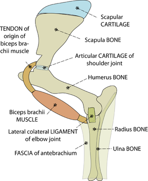
The tissues of the musculoskeletal system are bone, cartilage, ligament, tendon, fascia and muscle (Fig. 2.1). The non-muscular parts support the body passively by resisting forces that are applied to the body from outside (extrinsic) or those that are created intrinsically within the body. The most significant extrinsic forces are the earth's gravitational force on the mass of the animal, and the reaction of the ground. An animal, once it is born, must spend most of its life battling with gravity and the problems of contact with ground surfaces.
Animals also derive support from the activity of their muscles, as evidenced from the inability of an anesthetised animal to stand. This active type of support will be discussed in Sections 4 and 5.
- Fig. 2.1 Tissues of the musculoskeletal system
- This is a stylised view of the lateral aspect of the proximal left forelimb of the sheep. The skeleton is made of bones and cartilages. A combination of ligaments, muscles & tendons, and sheets of fascia, examples of which are shown, hold these together. Without these soft tissues around them, the jointed bones will not support the weight of the sheep.
The elasticity of tissues
An appreciation of the concept of elasticity is essential to understanding the mechanics of animals.
All materials are elastic to a lesser or a greater extent, even tissues like bone that seem to be stiff rather than elastic. The stiffness is only relative. After being deformed by an external force, all tissues must return to their original shape. If they did not, the body would be permanently deformed. Elasticity is a special function of the passive musculoskeletal tissues.
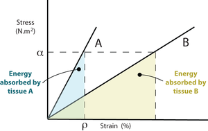
Elasticity is measured by determining the effect of stress, defined as force per unit area, on the shape of the material. When this stress acts in only one direction, this shape change is measured as strain, the distortion per original unit distance, expressed as a percentage.
At a particular percentage of strain, ρ, a stiffer material will store more elastic energy than a more elastic tissue. Suppose that at this strain percentage, the material can no longer be deformed without damage. Fracture will occur, and because the stiffer material releases more energy it will shatter rather that suffering a simple break. Bone fractures are discussed later in Chapter 3.
- Fig. 2.2 Stress, strain & elastic energy
- Two linearly elastic tissues A and B have stress - strain curves as shown. At any given value of stress, ρ, the energy absorbed by A, represented here by the area beneath the curve, is less than that absorbed by B. A is stiffer than B. If A and B were bones, A would be the more mineralised.
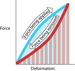
When an elastic material is strained, work is done on it and energy is stored in it. Elastic energy is a form of potential energy. A rubber ball falling on to a hard surface converts what was previously kinetic energy into elastic energy on impact. This elastic energy is released again as kinetic energy when the ball bounces. The ball does not, however, attain the same height as previously. The elastic framework of an animal’s body behaves similarly, as it bounces up and down during running (Fig. 2.4). Some of the kinetic energy is lost as heat. The less energy lost in this way, the greater the elastic resilience of the material. Resilience is the work recovered from a material in elastic recoil, expressed as a percentage of the work previously done in straining it (Fig. 2.5). Passive musculoskeletal tissues should be as resilient as possible, to conserve energy.
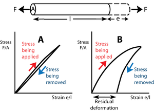
- Fig. 2.3 Elasticity
- The force F tenses a block of material of transverse sectional area A and length l, producing a deformation e. In Figure 2.3A, stress is proportional to strain. The slope of this line is the elastic modulus.
- Upon removal of the stress, the block returns to its original shape. The block is perfectly elastic. In Figure 2.3B, the elastic modulus is not constant; with more stress, a disproportionate deformation is produced.
- For this reason, and also because when the stress is removed some of the deformation remains, the block in this instance is imperfectly elastic. Such a residual deformation is not useful in animal mechanics.
Elastic resilience
When an elastic material is strained, work is done on it and energy is stored in it. Elastic energy is a form of potential energy. A rubber ball falling on to a hard surface converts what was previously kinetic energy into elastic energy on impact. This elastic energy is released again as kinetic energy when the ball bounces. The ball does not, however, attain the same height as previously. The elastic framework of an animal’s body behaves similarly, as it bounces up and down during running (Fig. 2.4). Some of the kinetic energy is lost as heat. The less energy lost in this way, the greater the elastic resilience of the material. Resilience is the work recovered from a material in elastic recoil, expressed as a percentage of the work previously done in straining it (Fig. 2.5). Passive musculoskeletal tissues should be as resilient as possible, to conserve energy.
- Fig. 2.4 Elastic resilience
- The work done in deforming the material is Fd, the product of force and distance. This is the area under the curve made during the application of the force (blue). The work done by the elastic restoring force is the area under the curve made during the removal of the deforming force (red hatching). In this example, these two areas are not the same. The difference in area is the energy lost as heat. The resilience is the red hatched area as a percentage of the blue area.
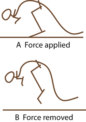
- Fig. 2.5 A hopping kangaroo
- Compare the angle of the hock joint when the limb bears weight, and when not weight-bearing. The passive tissues supporting this joint store energy in A and release it in B. At hopping speeds of between 10 and 35 km/h, kangaroo locomotion is remarkably efficient. This is due to the almost 100% resilience of the elastic support of the hock joint.
What makes materials elastic?
The elasticity of materials comes about in several different ways:
Molecular elasticity: Stress may produce a molecular change. The keratinous structures of mammals (hair, wool, hooves and horns) are elastic because the keratin molecule changes from a tight helix to an extended form when it is stretched.
Crystalline elasticity: Stress on a material such as steel results in changes in distances between atoms. A large stress produces only a small distortion. The elasticity is therefore low.
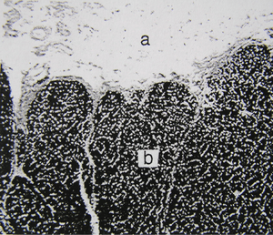
Rubbery elasticity: The elasticity of the most elastic materials results from the cross-linking of long, flexible, convoluted polymers. In rubber, these cross-links are formed by sulphur during the process of vulcanisation. Distortion of a block of rubber results in a distortion of each molecule, which is restored when the stress is removed. Cross-linking is necessary to prevent the molecules from slipping past each other. Elasticity of rubber is lost when there are too many cross-links or when the temperature is too low. Several biological materials show rubbery elasticity. In vertebrates, elastin is present in thin strands in loose connective tissue, providing the extreme elasticity of such tissues as the dermis. It predominates in the middle coat of the wall of large arteries and in the nuchal ligament of herbivores (Figs. 2.6, 2.7). It is not fibrous, but consists of thin homogeneous strands. Its elasticity is similar to that of lightly vulcanised rubber.
- Fig. 2.6 Elastin in the nuchal ligament of a sheep
- a. Loose connective tissues surrounding the ligament.
- b. Elastin fibres, stained with Verhoeff’s hematoxylin, in the ligament.
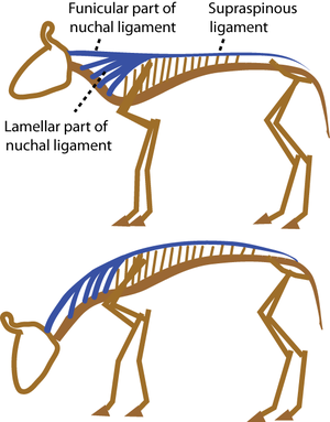
- Fig.2.7 A grazing cow.
- Herbivores have heavy heads held at the end of a long neck. As they flex their neck to graze, the nuchal ligament is strained by 50%. The elastic energy stored is released as the head is raised, so that little muscular effort is needed. A spring loaded garage door borrows this principle from the cow.
Fibrous elasticity: Polymeric molecules derive their elasticity by being arranged partly in ordered patterns to form crystalline regions, and partly with a random arrangement in amorphous regions. Examples of elastic materials of this kind include synthetic textiles like nylon and polyester, and natural ones like silk. Collagen, the main component of the passive musculoskeletal system, also has polymeric molecules, with the crystalline part composed of aligned and cross-linked molecules, appearing as fibrils (Figs. 2.8, 2.9). The molecules are aligned in a specific direction to form fibrils.
The significance of collagen
The fibrous elastomer collagen is by far the most predominant passive supporting substance in vertebrates. 20% of the protein of a mouse is collagen. Tendon, ligament and dermis are almost pure collagen, and it is a major constituent of bone and fibrocartilage. Few tissues lack it entirely. Collagen quality is of commercial interest because it determines the tenderness and appropriate cooking methods of different muscles, at different stages of growth.
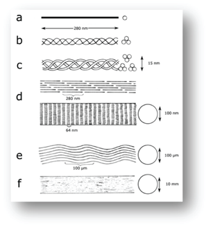
- Fig. 2.8 Molecular structure of collagen in a tendon, diagrammatic
- Tendon structure as envisaged by:
- a., protein chemistry;
- b., c., and d., X-ray diffraction;
- d., electron microscopy;
- e., light microscopy and
- f., as seen grossly in a large animal.
Collagen molecules, fibrils and fibres
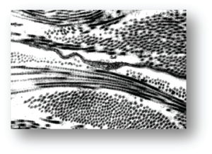
Collagen fibrils are formed when three tropocollagen molecules, each consisting of three helically arranged polypeptide chains 280 nm long, coil helically together, and align with other such "super helices". These polymeric molecules each overlap about one quarter of their length, so that an axial periodicity of 60-70 nm is visible with the electron microscope (Fig. 2.9). A collagen fibre is formed from bundles of fibrils (Fig. 2.8). Single collagen fibres are visible with the light microscope in connective tissues. They accumulate in bundles or sheets to form the gross structures ligaments, tendons and fasciae.
- Fig. 2.9 Collagen structure, viewed electron-microscopically
- Magnification x25,000.
- Lateral accessoriometacarpal ligament of a horse.
- Collagen fibrils, sectioned longitudinally and transversely (from Deane, Massey thesis, 1991).
Collagen matures with age
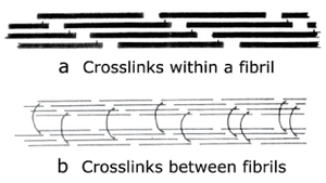
Stable aggregations of collagen molecules to form fibrils are achieved by cross-linking of the molecules. These give collagen both strength and elasticity. In newly formed collagen, the cross-links are relatively few, but with age, there is a significant increase in the number and the stability of the cross-links. This has two significant effects. Excessive stress on immature collagen contributes to tendon and ligament disease in young animals; the training of horses especially must take the aging of collagen into account. Also, variations in collagen cross-links cause the toughness associated with different cuts of meat, and with the increase in toughness in meat from older animals.
- Fig. 2.10 Collagen cross-links
- Crosslinks in immature connective tissue pass between collagen molecules within a fibril (a). The molecules are linked head to tail to form an infinite polymer.
- In a mature collagen fibre, (b), the crosslinks pass between the fibrils to link them in register.
- (Adapted from Bailey, 1988).
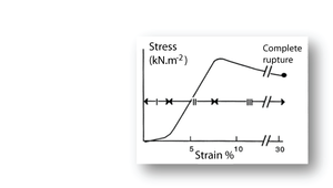
- Fig. 2.11 Tensile stress in collagen
- The stress–strain relationship in a bundle of collagen fibres, at a low rate of strain.
- Phase I: Rapid elongation as the "crimp" in the collagen fibres is eliminated. This part of the curve is smaller at the high strain rates likely to occur in vivo.
- Phase II: Stress is proportional to strain. This elastic phase of collagen is the phase most useful in vivo.
- Phase III: Breakdown of the crystalline components of the collagen fibres. Deformation takes place with progressively less stress.
Putting the stress on to collagen
When a collagenous structure, such as tendon, progressively undergoes tensile stress in a laboratory preparation, three stages o stress strain relationships are recognised (Fig. 2.11). During the first stage, the wavy pattern or crimp seen in bundles of fibres is removed. This crimp is probably due to an in–series elastic component, accounting for the high elasticity over this stage. This first stage is less apparent when the strain rate is high. Such a high strain rate is the likely situation in tendon in vivo. The second stage is the true elastic stage for collagen fibres. With stretch, the axial periodicity of the fibres is increased. The elasticity of collagen is about one three hundredth that of elastin. This makes it a suitable material for structures that must withstand large forces without stretching too much. In stage three, there is a loss of elasticity. The crosslinks between the fibrils have been broken by the stress and the material exhibits viscous flow. The strain remains after removal of the stress, defined as residual deformation in Fig 2.3.
Organisation of collagen in bone and fibrocartilage
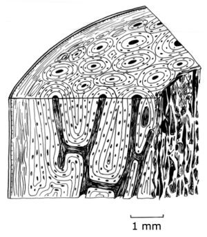
In both bone and fibrocartilage, collagen fibrils are embedded in a matrix. For bone, the matrix is made of mineral crystals and for cartilage the matrix is mucopolysaccaride. Bone and fibrocartilage are therefore both heterogeneous. Each is a composite material consisting of several different components. In bone, collagen forms one third of the weight and one half of the volume of the tissue. The arrangement of the collagen determines the quality of the bone. In the most structured bone, the collagen fibres are arranged parallel to one another in sheets, or lamellae, 5µm thick (Fig. 2.12). The alignment of the collagen alternates between the lamellae. In some bones, the lamellae form concentric rings around blood vessels. Each set of such rings is called an osteone. Not all bone is, however, lamellar bone; such highly organised bone is only common in larger reptiles and mammals. The predominant component of bone, by weight, is the organic part. Crystals of hydroxyapatite that lie between the collagen fibrils within each lamella form this. The resulting mineralised tissue is one twentieth as elastic as pure collagen in tension. Fibrocartilage contains collagen in a less organised pattern than lamellar bone. The more elastic type of cartilage contains elastin also. The matrix of cartilage is a polymer made up of proteins and polysaccharides in hydrated complexes, known as mucopolysaccharide.
- Fig. 2.12 Bone structure
- A magnified, schematic view of a section from the shaft of a bovine femur.
- a periosteum
- b lamellar bone
- c osteone
- d vascular canal
The advantage and organisation of composite materials
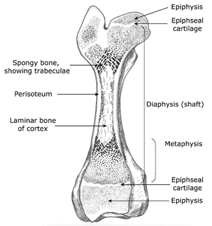
As examples of composite materials, the physical properties of bone and fibrocartilage are unlike those of either component taken alone, and are not the sum of the two taken together. Collagen fibres resist tension forces and hydroxyapatite resists compression forces. The composites, bone and fibrocartilage may therefore be likened to manmade materials such as ferroconcrete, fibreglass or filled rubber. The discovery of these revolutionised construction of bridges, boats and tyres, as was animal construction revolutionised when bony skeletons were invented much longer ago. Structures made up of bone or fibro-cartilage are seldom homogeneously constituted. Their composite materials have specific orientations and densities, resulting in compact or spongy bone, or hyaline cartilage with little collagen or dense fibrocartilage. The elasticities and strengths of these depend on both the orientation of the force to the direction of the fibrous component, or "grain", and the proportions of each component. For instance, bone lamellae are densest around the surface and along the shaft of a bone (Fig. 2.13). The reasons for this are apparent once the forces within the structure are considered.
- Fig. 2.13 Structure of a long bone
- The architectural requirements specify that only sufficient material should be used to allow for stresses the bone is expected to tolerate. Thus, the extremities are composed of spongy bone internally, the shaft is osseous only on the outside, and the dense laminar bone of the shaft is thickest halfway along its length. During growth, an increase in the length of the bone occurs by ossification of cartilage, produced from the epiphyseal line, in the metaphyseal region. This growth is minimally affected by stresses in tendons and ligaments, because these structures are attached to the epiphyseal regions beyond the epiphyseal lines.
Compression and tensile strength of bone and cartilage
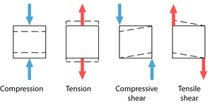
The strength of a tissue is determined by measuring the minimum stress needed to produce permanent deformity in the material. Deformation comes about by pairs of opposing forces that cause compression, tension or shear (Fig 2.14). The compressive strength of fresh compact bone loaded parallel to the grain is about 170 MN.m-2. This is impressive, considering that the compressive strength of marble and granite is little more, at 200MN.m-2. Cartilage has a compressive strength lower than bone.
• Fresh, compact bone loaded parallel to the grain has a tensile strength of 80MN.m-2. For steel it is 500MN.m-2. Again, cartilage has a compressive strength lower than bone.
• The resistance of compact bone to shear may be as low as 50MN.m-2 if stressed parallel to the grain, and as high as 120 MN.m-2 if stressed transversely to the grain. Cartilage, tendon and ligament have less resistance to shear.
If bone is mechanically superior to other materials, why is it not used more often for preference?
- Fig. 2.14 Types of stress
- Pairs of forces can exert three types of stress on solids
Weight economy and the choice of building materials
In nature, the most successful animal would be expected to economise on the use of building materials. Living in a highly competitive athletic environment, neither the hunter of the hunted can afford the luxury of excessive inertia-producing mass. Wild animals are lean and mean. The successful animal will employ in any given situation the least dense material for the task, in relation to the maximal mechanical demands that are made. With regard to weight economy, therefore, the specifications of the animal machine will use bones where high compression and shear forces are to be resisted, cartilage where these forces are lower and where lightness and elasticity are required, and pure collagen fibres where tensile forces alone are to be resisted. Because animals economise on materials, the size and shape of their various parts indicate to us much about their function. Since its establishment as the first modern science by Vesalius in 1543, anatomy has depended very much on this principle.
Grace and coordination: the significance of strain rate
In locomotion, and when the animal must absorb accidental impact, dynamic, rather than the static physical properties described above are much more relevant. A small stress suddenly applied may do more damage than a large stress gradually applied. To break a piece of string, it is useful to apply a high-tension strain rate (give it a sudden jerk) as well as shear (pull the string over the edge of a table). Bone fractures are more likely when movement becomes less coordinated. The actual strain rate is difficult to measure in the living animal under the conditions in which the supporting tissues are used. Nevertheless, we can appreciate that an animal should run in such a way that strain rates are as low as possible by eliminating hard impact with the ground. Animals generally move smoothly and gracefully.
The advantages and disadvantages of stiffness
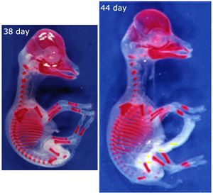
A major dynamic physical property of the supporting tissues is their energy absorption ability (Fig. 2.2) or stiffness. The stiffer the material, the less kinetic energy it is able to absorb. Since bones function as levers, stiffness is a desirable property; the higher the proportion of mineral, the stiffer the bone. Bone mineral first appears in bones of the developing fetus at sites where stiffness is needed most. This is either for protection, such as in the cranium to protect the brain from external pressure, or to aid correct development, as in the long bones of the limbs, the shape of which is necessary for the correct form of the muscular system (Fig. 2.15). The most highly mineralised bones in the body are the aptly named petrous temporal bone and the auditory ossicles, both involved in the detection and interpretation of sound waves. These bones assist the process of hearing best if they manage to avoid the absorption of the energy of sound waves. But because of this, they are brittle, and must be protected from other forms of mechanical stress by being enclosed by softer bone.
- Fig. 2.15 Ossification of limb bones
- These views of a sheep fetus at 38 and 44 days after conception have the mineralised bone stained with alizarin. They show which bones and parts of bones need the stiffening properties of hydroxyapatite crystals to ensure normal development, even though limb bones are not needed to support the weight of the animal at this stage.
- Why are the bones of the skull and thorax relatively well developed?
Energy economy – getting the most out of legs
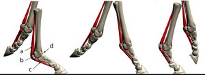
The unmineralised collagenous structures, tendons and ligaments, absorb energy during locomotion as elastic energy, which reappears when the stress is removed, mainly as kinetic energy and partly as heat (Fig. 2.5). The collagen in the limb of a horse behaves like the spring inside a pogo stick (Fig. 2.16). It is the elasticity of legs that offsets for them the inherent disadvantages they have when compared with that unique human invention, the wheel.
- Fig. 2.16 Elasticity of collagen"'
- Action of the suspensory ligament a.,
- the proximal sesamoid bones b,.
- and the sesamoidean ligaments c.,
- of the fetlock joint d. of the horse at three stages of the stride.
- During a fast gallop and when landing from a jump, the ergot on the palmar surface of the fetlock joint contacts the ground
Tissue proportions and the absorption of energy
The greater the mass of a particular material, the more energy it can absorb. The weight of a bone, or for that matter that of the entire skeleton within the body, is understandably dependent more on how much energy need be absorbed during exercise, rather than by the ability to resist a static load. Body design is not well explained by considering only static forces. This will be discussed later in relation to the weight of the skeleton in animals of different body size, in Chapter 7.
The economical design of bones
A bone must contain the minimum material necessary to allow for the combination of compression, tension and shear forces to which it is subjected. Economic gain can be achieved by organising the distribution of ossified and nonossified tissues within a bone, or by designing the shape of the bone to take account of the predominant tension, compression and shear force couples that are applied to it. The next chapter shows how whole scientific disciplines, the osteological aspects of anatomy, archeology and paleontology, are based on this premise.
The design of the passive supporting tissues
Osteology: bones provide long-lasting clues to ancient forces
The study of bones, osteology, is often the only opportunity to deduce the natural history of an animal long since dead. The oldest quadruped bone fossils are 350 million years old (Fig. 3.1). The distribution and density of mineralised tissue indicate the magnitude and direction of the forces acting on a bone in life, no matter how long ago these forces were applied.
- Fig.3.1 Ichthyostega
- The oldest known tetrapod is a late Devonian amphibian that measured about 1 m in length.
Sculpture within bones
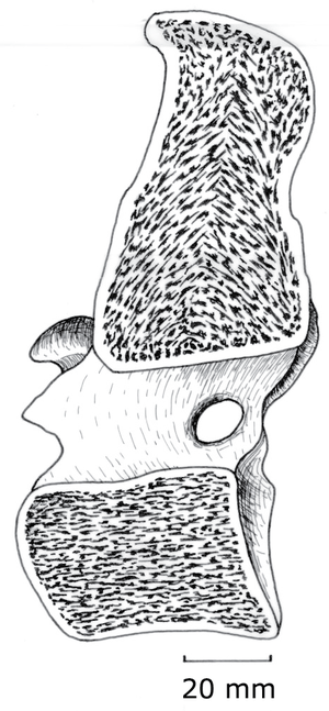
The combination of lightness and compression strength is obtained by internal sculpturing. Trabeculae (Latin, little beams) are oriented parallel to the compression forces. These forces act, for instance, between opposing ends of the bodies of vertebrae, & therefore the trabeculae are parallel to the axis of each vertebral body (Fig. 3.2). At the end of a long bone, the compress-ion force transmitted across a flexed joint is not parallel to the shaft, and will vary in direction. Here, the design most economical of material is a network of interconnecting trabeculae following the compression stress lines (Fig. 2.8). Study the pattern in a long bone that has been sectioned longitudinally.
- Fig.3.2 Trabecular compression lines in bone
- A median section of the 10th thoracic vertebra of the horse, showing trabeculae within the vertebral body directed along the long axis of the body.
Design to resist bending in one plane
Couples acting in planes parallel to the length of a bone result in bending, which involves a combination of compression (on the inside of the bending curve) and tension (on the outside of the bending curve). If the bending is predominantly in one plane, the shape of the bone is such that the longer dimension is oriented in the same plane as the bending couple. Thus the zygomatic arch is a bony beam turned on edge to the force acting on it, as are the body and the ramus of the mandible, the spinous and the transverse processes of the vertebrae, the scapula, and the wing of the ilium.
Design to resist bending in several planes
The long bones of the limbs, however, must resist bending forces in many directions. Compression and tension due to bending are greatest towards the outside of a bone; hence a hollow cylinder achieves the most strength for the least material. The same principle applies in the design of bamboo and scaffolding. Maximum bending stress occurs half way along the length of the shaft, and here the cortical bone is thicker and denser (Fig. 2.8). An analogous manmade structure is the leafed spring of a car. In this case, one leaf is sufficient at the ends, but all the leaves overlap in the middle of the spring.
Design to resist shearing
Shearing forces are applied to bones at the sites of insertion of tendons and ligaments. Resistance to these forces is enhanced by localised thickenings of the bone. Tubercles such as the ischial tuberosity and the greater trochanter of the femur (Fig. 2.8), which serve to increase the torque of muscles acting about a joint, are large because the shearing stress is great. Couples acting in planes at right angles to the length of a bone result in twisting, which also shears the material. The shearing stress is, as for bending, greatest at the outside, and zero along the central axis of the bone. Hollow shafts give strength with lightness in twisting as well as in bending, and again, such stress is greatest midway along the length of the bone.
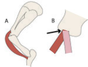
- Fig.3.3 Attachments of tendons to bone
- The direction of the tensile force in the tendon of origin of the biceps brachii muscle of the horse does not change with changing angulation of the shoulder joint, because the tendon bends around the intertuberal groove of the humerus (A). Were this not so, the stress would be concentrated on one part of the junction of bone and tendon (B, arrowed).
The junction of bones with ligaments and tendons
Where tendons and ligaments are attached to a bone, tension, as well as shearing, occurs. At the junction, the collagen fibres of each tissue pass uninterrupted from a mineralised tissue to a non-mineralised tissue. At these junctions, the angle at which tension and shearing occurs must not change with different positions of the limb (Fig. 3.3). This is a special requirement in the design of joints and the location of tendon and ligament attachments .
Elastic energy and bone fractures
Fractures occur when the elastic energy (the area under the stress-strain curve in Fig. 2.2) builds up to a point beyond which any recovery is possible. Highly mineralised bone breaks more easily, for the same percentage of strain. Elastic energy can also be increased by a higher loading rate. Bones fracture most under sudden, violent forces. The same forces applied in a slow, uniform manner would not cause as much injury. A fatigue fracture occurs when muscle fatigue results in, for instance, stumbling, and hence abnormally high loading rates. Damage to bone from external forces depends on the speed, from slight damage due to low speeds of impact, to more damage when an animal is hit by a car, is kicked, or runs into a fence, to the very high energy fractures caused by a bullet.
Kinds of fractures
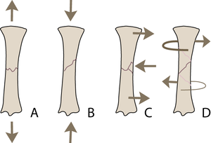
Bone, we have noted, is stronger under compression than under tension, while shear is intermediate. Appropriate combinations of forces cause tensile fractures (Fig. 3.4 A) in bone mainly at the sites of attachment of tendons and ligaments. Common sites of fracture are, in the horse, the proximal ulna, the patella, the proximal sesamoids, the calcaneus and the accessory carpal bone. Such fractures are usually transverse. Compression fractures, (Fig. 3.4 B) by contrast, are usually oblique, at an angle of 45° that corresponds to the plane of maximal shear stress due to the compressive load. Because bone is damaged more by tension than compression, bending fractures (Fig. 3.4 C) begin on the tension side, are transverse where there is tension, and oblique on the compression side. In torsion fractures, (Fig. 3.4 D) shear stress occurs over the entire shaft of a long bone, and is greatest at the periosteal surface. The result is a spiralling fracture.
- Fig.3.4 Ways in which a long bone may fracture
- The type of external load applied to a bone will determine the pattern of the fracture:
- A Tension
- B Compression
- C Bending (tension and compression)
- D Torsion (shear).
- The type of external load applied to a bone will determine the pattern of the fracture:
The role of tendons
Tendons transmit to bones the force produced by muscles. Muscular force is thereby concentrated on to a small area of the skeleton, contributing to precision of movement and allowing several muscles to act on the same structure in different ways. By the use of tendons, the mass of a muscle may be at a considerable distance from the site of skeletal movement, thereby controlling weight distribution and contours of the body. Consider the insertions of the extensor muscles of the hip joint.
Antifriction devices associated with tendons
Limbs are, of course, not straight, and the angles of joints can change markedly. Tendons allow the transmission of a force round these angles. The simplest way to smooth their passage is to provide a cushion. This is a bursa (Latin, wine sac made of goatskin), a pouch lined by synovial membrane and filled with synovial fluid. This lies between the tendon and the bone (Fig. 3.5 a), or it may wrap around the tendon to form a synovial sheath (Fig. 3.5 b). Sheaths are often held in place by transversely arranged collagenous structures, retinacula. A further adaptation occurs when the surface of the bone becomes changed to articular cartilage and forms one boundary of the bursal cavity. A pulley-like arrangement is formed (Fig 3.5 c).
- Fig.3.5 Structures reducing friction between tendon and bone
- (a) to (d) represent increasing complexity
- Left side: longitudinal sections of the tendon
- Right side: transverse sections of the tendon
- Note that that the opposing surfaces of a synovial space are normally in contact.
- a. bursa
- b. synovial sheath and retinaculum
- c. articular cartilage, bursa and retinaculum
- d. sesamoid bone, articular cartilage, synovial joint and collateral sesamoid ligaments
Shearing within tendons
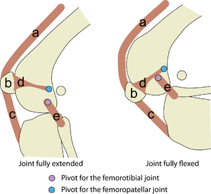
Loaded tendons that are straight sustain only tensile forces, but where a tendon bends shearing forces also occur. Accordingly, tendons compensate by becoming thicker at such places. If forces other than tension are particularly severe, small bones, which are better able to withstand compression and shear, interrupt the tendons. These are called sesamoid bones (Latin, resembling a sesame seed) (Fig. 3.5d, & 3.6). A bone inserted into a tendon also creates the possibility of attaching ligaments to hold the tendon precisely in place. These are collateral sesamoidean ligaments (Fig. 3.6). Both the sesamoid bone, and the bone with which it is in contact, have articular cartilage on their opposed surfaces. This arrangement of a synovial sac interposed between two bony surfaces covered by articular cartilage constitutes a synovial joint. Examples of sesamoid bones in the dog are those interposed in the tendon of insertion of the quadriceps muscle at the stifle joint (the patella) (Fig 3.6), and the bones interposed in the tendon of insertion of the Interosseous muscles at each of the metacarpo- and the metatarsophalangeal joints (the proximal sesamoid bones (Fig. 2.16)). In both these examples, the synovial pouch of the seamoid bone is continuous with the pouch of the adjacent joint.
The lubrication of joints: multigrade specification
The lubrication fluid of bursae, synovial sheaths and joints is secreted from protrusions of synovial membrane, synovial villi, located in loose parts of the joint capsule away from any compressed surfaces. This is synovial fluid. In a normal synovial sac, only a small amount of fluid is present. The viscosity of this clear or pale yellow liquid is more during slow movement, which is when the rate of shear is low. But when the shear rates are highest, the viscosity becomes much lower. The fluid drag and hence the supporting ability of the joint is therefore greatest when the limb is quietly bearing weight; the impedance is conveniently reduced for fast movements. Lubrication is effected in two ways, so that the pressure in the fluid film supports the load. Not only does a film of synovial fluid separate opposing articular surfaces (fluid film lubrication), but also a single layer of glycoprotein molecules of synovial fluid is absorbed into the surface of the articular cartilage and protects the surfaces against wear (boundary lubrication). The resulting lubrication is termed elastohydrodynamic. The cartilage surfaces are elastic; the deformation at contact increases the surface area and the lubricant escapes less readily; and the load-bearing capacity of the joint is greatly increased.
- Fig.3.6 The largest sesamoid bone
- The patella (b) is interposed in the tendon of insertion of the quadriceps muscles (a), that insert on the tibial tuberosity through the patellar ligament (c). The patella is held in place by collateral femoropatellar ligaments (d), and the hinge movement of the joint is maintained by the collateral femorocrural ligaments (e).
The resistance of joint surfaces to wear
Large repetitive compression and shear forces between opposing bones are catered for by an elastic surface 1 to 7mm thick composed of hyaline cartilage. This cartilage is unusual in that it has no perichondrium. The collagen within this articular cartilage differs from that of fibrocartilage in that the fibrils no not aggregate to form fibres. They do, however, align parallel to the surface for a shallow depth over the articular surface, and in a deep, thick zone are perpendicular to the surface and are continuous with the collagen of the underlying bone. Since articular cartilage is 70 to 80% water, its elasticity probably incorporates hydrostatic properties as well. While joints usually cope well with a lifetime of wear, the demands of the breeders and trainers of athletic and working animals are often overoptimistic. Thus injuries to joints arise not only from accidental trauma but also because of genetic selection for high performance, and from overuse.
Orthopedics: assisting natural wear
In various ways, not only joints, but also all other components of the passive musculoskeletal system of these animals can fail. While natural repair is often possible, with rest, diverse orthopedic techniques have been developed to save valuable animals. The application of each of these techniques depends on an understanding of the mechanical principles of the structures needing repair, and the materials used to assist. An orthopedic surgeon constantly depends on good anatomical knowledge.
Force production in animals
A muscle either makes movement, or prevents it: Action or heat?
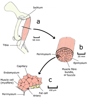
Forces produced within muscles achieve animal posture and motion. A muscle (Fig 4.1 a, b) consists of a large number of fibres (Fig 4.1 c) arranged in such a way that a force is developed between the two ends of the muscle when the fibres are stimulated by electrical impulses coming from nerves. This force may cause movement, but if the force is no greater than opposing forces either within the animal's body (i.e. from antagonist muscles) or acting externally on the animal's body (such as the force of gravity), no movement will result. Mechanical and heat energy are generated from the chemical energy supplied as nutrients to the muscle. If no movement results from the generation of a muscular force, no mechanical work is done, and all the energy must be released as heat.
- Fig. 4.1 Muscle structure 1
- The semitendinosus muscle of a dog, as seen by the unaided eye (a & b), and in transverse section with the light microscope (c).
The contractile proteins of muscle
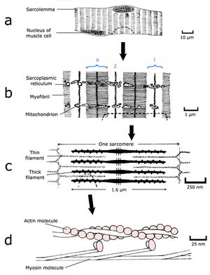
To understand the nature of a muscular force, we must appreciate the molecular and filamentous structure of muscle. Muscle is a machine largely constructed from two proteins, actin and myosin. Actin can exist in a globular form of molecular weight 45,000 and a diameter of 5.5 nm, which readily aggregates to form a long filament (Fig. 4.2 d), each filament contains two strands of spherical actin molecules, twisted on each other. In muscle, the form of these chains is regulated by the presence of two other proteins, troponin and tropomyosin. Myosin is a larger protein, with a molecular weight of 500,000 and a more complex shape. A molecule resembles a thin rod with two small globular “heads” at one end (Fig. 4.2 d). Under the right conditions these molecules aggregate into a sheaf, a cigar shaped structure studded with projections of myosin heads along its length. Because the heads are directed towards the ends of the structure, there is a bare zone in the middle (Fig. 4.2 c). To electron microscopists, the accumulated actin molecules and their associated proteins are known as thin filaments, and the myosin structures as thick filaments. Thin filaments are organised around the thick filaments in a regular hexagonal array. In electron micrographs of muscle, the projections of the thick filaments appear as minute crossbridges that seem to link the thin and the thick filaments.
- Fig.4.2 Muscle structure 2
- Skeletal muscle fibre in longitudinal section;
- a, as visualised by the light microscope;
- b & c, by the electron microscope; and
- d, as reconstructed from crystallographic X-ray
The appearance of muscle using electron microscopy
Thick filaments are 1.6 µm long, and are joined by a meshwork, anchoring the ends, called a Z disc (Fig. 4.2 c). The serially repeating filamentous array was visible to the early light microscopists, especially using polarised light. They called the region occupied by the thick filaments an anisotrophic or A band, and the region occupied by the thin filaments an isotrophic or I band. The Z disc appeared as a narrow dark band dividing the lighter I bands (Fig. 4.2 b). The whole filamentous structure between adjacent Z discs is called a sarcomere.
What makes the striations in skeletal muscle?
Sarcomeres are added in series along the length of the muscle fibre; a relaxed fibre 3 cm long would contain about 15,000 sarcomeres in series. Within the fibre, the myofilamentous pattern is broken up by other components of the fibre (mainly sarcoplasmic reticulum and mitochondria) to form bundles of myofilaments called myofibrils (Fig. 4.2 b), each about 0.5 µm in diameter. However, the greatest proportion of the transverse sectional area of a muscle fibre, and indeed of an entire muscle, is occupied by myofilaments.
Sliding filaments and the site of the contractile force
Muscle contraction is caused by a sliding of the two sets of filaments past each other. The action sites are the crossbridges between the heads of the myosin molecules and the thin filaments. Crossbridges on opposite ends of the thick filaments are directed in opposite directions. Stimulation of activity at the crossbridges therefore creates a mechanical force tending to bring the thick and thin filaments into greater overlap, decreasing the distance between the Z discs, or sarcomere length, and shortening the muscle. The sarcomere is therefore the fundamental contractile unit of muscle.
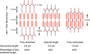
- Fig. 4.3 Sliding filaments in muscle
- The sarcomere can normally contract to 44% of its fully stretched length. At its optimal length of 2.2 µm, the thin filaments are maximally in apposition with the crossbridges of the thick filaments.
Linear motors
A muscle is a linear motor. Most man-made motors are not linear, since they take advantage of the wheel, a device not possible in animals. A man-made machine using a linear motor is the magnetic railway, where a magnetic field both lifts the train off the track, and provides a linear thrust. If we accept the fossil record, the muscle machine preceded electric motors and internal combustion engines, and indeed the also very modern invention of the wheel, by 70 million years.
The force of a muscle depends on sarcomere length
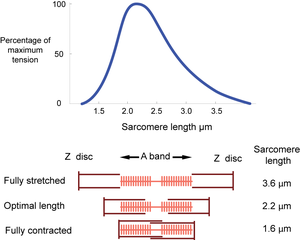
The dimensions of the sarcomere determine the extent to which muscle cells can be stretched or contracted. When fully stretched the sarcomere length cannot exceed 3.6 µm without the fibre losing the ability to contract again (Fig. 4.3). As the muscle contracts, more and more crossbridges are brought into use. The force produced increases (Fig. 4.4) until all the crossbridges between thick and thin filaments can be used. At this point, simply because of the dimensions of the filaments, the sarcomere length is 2.2 µm, i.e. 59% of the fully stretched length. This is the optimal length. With further contraction, no more crossbridges can be used, in fact there is interference by overlapping of thin filaments and the force produced declines. When the sarcomere length is 1.6 µm, the muscle can contract no further without penetration of the Z discs by thick filaments, and resulting damage. The sarcomere, and hence the entire muscle cell in which the sarcomeres are in series, is now 44% of the fully stretched length. These measurements made by electron microscopists can be verified by using a device as simple as a ruler, since they agree with measurements of the range of contraction of muscle fibres (and the macroscopically visible fibre bundles) in the limb muscles of animals.
- Fig. 4.4 Tension in muscle
- Tension is maximal at a sarcomere length of 2.2 µm. A muscle, therefore, will have only one optimal length for developing tension.
Getting the most out of restricted muscle performance
The stage of contraction at which the force produced by a muscle is optimal is therefore quite limited. The implications of this in the design of the musculoskeletal system will be discussed later in section 7.
Muscle mechanics
Contractile units in series and in parallel
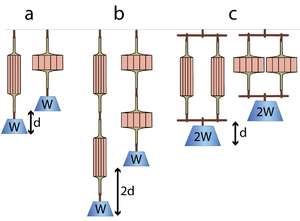
The effect of arranging sarcomeres in series can be visualised by considering two muscles doing work by lifting a weight. In Fig. 5.1 a, a single muscle contracts maximally to lift a weight W through a distance d. If two similar muscles are arranged in series (Fig. 5.1 b), both muscles act equally on the weight. Each contracts the distance d, so the total distance contracted is 2d. The total contractile force is equal to the contractile force of one of them, but by an in-series arrangement, the range of contraction has been doubled.
Similarly, we can consider two muscles in parallel (Fig 5.1 c). When they lift a weight W, each muscle shares the load. Hence each has half the load (W/2) and therefore contracts half the distance (d/2). It would take a load of 2W to make the muscles contract a distance d. So, if sarcomeres in muscle are arranged in parallel this would result in a doubling of the force produced, but the range of contraction in this case would be no greater than that of a single muscle.
- Fig 5.1 The effect of the strength of muscles in series and in parallel
- A muscle contracts a distance d and lifts a weight W against gravity (a). When two such muscles are in series, the distance lifted is 2d (b). Each muscle is effectively loaded as in (a). When the muscles are in parallel, as in (c), the load is shared and the muscles can lift twice the weight 2W through their contraction distance d. Note that the work done (2d x W, or d x 2W) in lifting the weight by pairs of muscles is the same regardless of their configuration. Similarly the work done by a muscle depends on the number of contractile units (sarcomeres) within it (hence its weight), and not on the geometrical arrangement of the contractile units (or, in the arrangement shown in the diagrams, its shape).
Movement, strength and work
Range of contraction is therefore proportional to the number of sarcomeres in series, or the length of the muscle fibre. The force produced (strength) is proportional to the number of sarcomeres in parallel, or, since the contents of a fibre are predominantly myofibrils, to the transverse sectional area of the muscle fibre. The strength of muscle is approximately 0.3 MN.m–2 of transverse sectional area. Note that the work done by a muscle (force x distance) is the same in both cases (Fig 5.1). The possible work that a muscle can do, or mechanical energy that it can generate, is proportional to the total number of sarcomeres or, in other words, to the mass of the whole muscle.
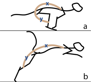
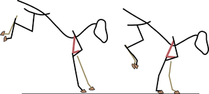
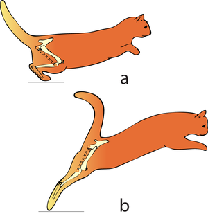
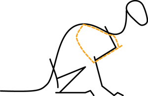
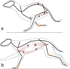
Consider two activities of a cat. A large force is required to accelerate the mass of the body from the position of crouching, ready to spring. The more sarcomeres that are in parallel, i.e. the greater the transverse area of the muscles brought into use, the greater the acceleration. A cat in this stance arranges its hind limbs and back to recruit as many as possible sarcomeres in parallel (Fig 5.2 a). It also positions each sarcomere at the optimum length for the development of a contractile force (Fig 4.3). You can easily observe this by watching a kitten at play, pretending to stalk and spring.
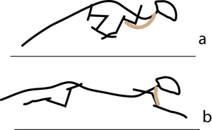
A galloping cat protracts the forelimbs to lengthen the stride as much as possible (Fig 5.3). This movement demands of the muscles protracting the forelimbs a large range of contraction. The muscle involved must have as many as possible sarcomeres in series.
- Fig 5.2 Sarcomeres in parallel
- In (a), a cat is crouching ready to spring. The propulsive force will be provided by the extensors of the vertebral column x, and the extensors of the hip y. These are the most massive muscles in the body, and a high number of their sarcomeres are therefore in parallel. The result of the contraction is seen in (b).
- 5.3 Sarcomeres in series
- In the stage of the gallop of the cat in which the forelimb is retracted, the brachiocephalic muscle (dotted line) is fully stretched (a). When the forelimb is protracted, (b) this muscle is fully contracted. During contraction of the muscle, the forelimb is not in contact with the ground; the muscle accelerates only the limb and not the whole cat. The emphasis is therefore on range of movement rather than strength; the sarcomeres in this muscle are therefore predominantly in series.
Each muscle is a unique organ delivering unique torques
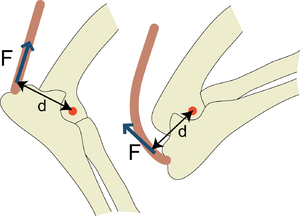
Muscle fibres are incorporated into organs, which are recognised anatomically as muscles. These organs are separated by connective tissue sheets or fasciae that permit individual movement. Although several muscles might act over the same joint (for instance there are at least 17 named muscles acting over the hip joint of the dog), each muscle can be defined by its origin and insertion. This endows some joints with a variety of movements (Chapter 8), usually about a point at the centre of an arc about which the joint hinges or rotates. This point is therefore a joint pivot, and the muscles acting over the joint provide turning movements or torques in directions dependent on their skeletal attachments (Fig. 5.4).
- Fig 5.4 Torque in the elbow joint
- Torque is the product of the force and the perpendicular distance from the pivot it acts over. In this hinge joint, the pivot is in the centre of an arc formed by the condyles of the humerus. The protruding length of the olecranon process of the ulna (d) increases the torque (F x d) that the force (F) produced by the triceps brachii muscle is able to apply to the elbow in attempting to prevent the forced flexion of the elbow joint, as demonstrated here.
Torque and equilibria
Torque is the product of the force and the perpendicular distance from the force to the pivot (Figs. 5.4 and 5.5). The concept of torque is much more useful in estimating the effects of muscles on joints than a concept of levers, since forces often act in an arc about a joint pivot, for a reason already discussed (Fig. 3.3).
In a state of equilibrium, the torques about a pivot balance each other in all directions. These torques usually include that produced by the force of gravity. The torque of postural muscles opposes the gravitational torque.
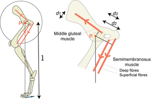
- Fig 5.5 The effect of the site of muscle attachments on the torque produced by muscles over the hip joint
- The turning effect of a force about a pivot P, the torque, depends on the magnitude of the force and its perpendicular distance from the pivot d1, d2, d3 or l. In the diagram, the middle gluteal and the semimembranosus muscles turn the femur about the hip bone. Assuming the forces to be equal, the magnitude of the torque is greatest for the superficial part of the semimembranosus muscle and least for the middle gluteal muscle since d2 > d3 > d1. The torques of each of these muscles summate, and produce a propulsive force on the ground. The perpendicular distance of the propulsive force on the ground from the pivot, l, is much greater than the perpendicular distance of any muscle from the hip.
In propulsion, the torque of certain muscles at a pivot results in a force where the foot contacts the ground (Fig. 5.5). The propulsive force at the foot is less than the force of muscle contraction. The advantage is, however, that the range of movement at the foot will be greater than the range of contraction of any of the muscles. The power for propulsion comes from a concentration of forces about the hip (Fig. 5.2). Use the concept of torques to consider how limb design must optimise the muscular forces that accelerate hip extension, while optimising stride length. The properties of limbs are discussed further in Chapter 8.
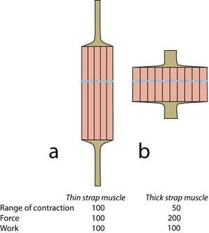
- 5.6 Strap muscles
- Diagrammatic representations of two muscles of similar mass but different shape. Mechanical values are given for the muscles relative to 100 for the muscle a. The “functional transverse area” is indicated by the dotted lines. Tendons of origin and insertion must be related in thickness to the strength of the muscle in series with them.
Fibrous architecture of muscles
An equally important aspect of design affecting strength and range of movement of muscles is their fibrous architecture. Here, "fibrous" refers not only to muscle fibres, but to collagen fibres also. In the simplest case, fibres within the muscle are aligned parallel to the force vector of the whole muscle. Such muscles are called strap muscles (Fig. 5.6). Their range of contraction and their strength depends on their shape, because this determines the number of sarcomeres in series or in parallel. Only one combination of range and strength will fit into a particular space in the body. The use of strap muscles in musculoskeletal design is therefore limited.
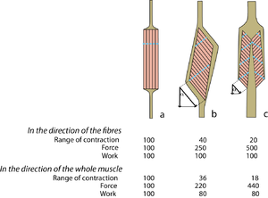
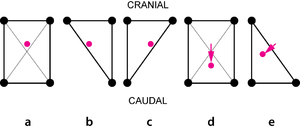
Muscles of the same shape can behave very differently Figure 5.7 compares three muscles of the same mass, and the same general shape. Each of these muscles could fit into the same space in the body. If the fibres are parallel to the force vector of the whole muscle (Fig. 5.7 a), the number of sarcomeres in series is maximal, and the number of sarcomeres in parallel is minimal, for a muscle of this shape. The fibrous architecture of such a strap muscle gives maximal range of movement, and minimal strength.
If the fibres are aligned at an angle to the force vector of the whole muscle (Fig. 5.7 b, c), the effective force and range of movement of each fibre is reduced since it is proportional to the cosine of this angle. Compared with Fig. 5.7 a, the number of sarcomeres in series has been reduced, and the number of sarcomeres in parallel has been increased. Thus the force has been increased in spite of the angulation of the fibres, but the range of contraction has been decreased. In the direction of the fibres, the work done during contraction is similar for the three muscles, since their mass is the same.
- Fig 5.7 Pennate muscles
- Diagrammatic representations of three muscles of similar mass but different shape but of widely varying fibrous architecture. Approximate values for range of contraction, force and work are given for the pennate muscles b and c, relative to those of the strap muscle a = 100, when the angle of pennation = 25°. The "functional transverse area" is indicated by the dotted lines. Note that the effect of pennation has been to reduce the range of contraction and the work effective in the direction of contraction, but to increase the force. Note also that the more sarcomeres that are in parallel within the muscle, the more tendinous apparatus must be in series with it.
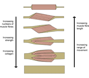
- Fig 5.8 Extremes of pennation
- The properties of a muscle vary with the proportion of collagen built into its architecture, even though its external appearance, as judged by its shape and size, remain much the same.
Some muscles look like feathers
Muscles with the fibres at an angle to the force vector are termed pennate (L. penna, feather). Not all the work done in this type of muscle is useful in the direction of action of the muscle. Tendons of pennate muscles may be central (Fig. 5.7 c) or they may form a tendinous sheet on the surface of the muscle (Figs. 5.7 b, c), called an aponeurosis (Gr. apo, from; neuros, nerve) because the ancient Greeks did not distinguish properly between nerves, ligaments and tendons. The appearance of the fibrous connective tissue of an aponeurosis may at first give a misleading impression of the arrangement of the muscle fibres within.
Pennate muscles need this collagenous framework to link the increased number of sarcomeres in parallel. Also, because of the increased force of pennate muscles, there must be a proportionate increase in the strength, and hence the transverse sectional area, of tendons of origin and insertion (Fig. 5.7).
When muscles become ligaments
With increasing pennation, the range of contraction decreases and the strength increases (Fig. 5.8). The limit is reached when the muscle fibres become too short to function and the muscle becomes entirely ligamentous. This occurs in certain muscles as an effect of body size (Chapter 7). How do contracting muscles fit into a limited space? Pennate muscles change shape during contraction in a manner different from strap muscles. A contraction of a strap muscle by 30% results in an increase in transverse sectional area of 30% since the volume of the muscle is constant. On the other hand, it is possible for a pennate muscle to contract without an increase in the transverse sectional area of the muscle (Fig. 5.9). This is important where muscles must lie in a constricted region, such as within the antebrachial or crural fascial sheaths.
Note that the decreased range of movement of a pennate muscle can be compensated for by an appropriate change in its skeletal attachments. (Fig. 5.5); a strong pennate muscle, such as the deep gluteal muscle, can still deliver an effective propulsive force at the foot even though its force is directed close to the pivot at the hip.
- Fig 5.9 Contraction of a pennate muscle
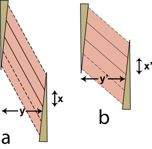
- A fibre maintains a constant volume during contraction. Its areas of attachment to the tendons of origin and insertion are also constant. This figure shows a single muscle fibre with solid outlines in only two dimensions, stretched in (a) and contracted in (b). The following argument is, however, correct for a three dimensional structure. Because the area of the parallelogram shaped fibre is constant, its length of attachment x is constant, and its area is x. y, y = y'. Therefore although the individual fibres of the muscle increase in thickness during contraction, the pennate muscle as a whole does not.
Muscle metabolism
Fast and slow twitch muscles
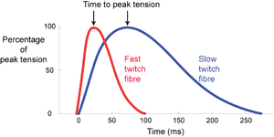
Skeletal muscle fibres of mammals, with few exceptions, respond to stimulation by an electrical impulse arriving at their surface with a twitch. The impulse becomes propagated throughout the fibre, the fibre contracts as a unit, and then relaxes as a unit. This is in distinction to a non-propagated impulse found in the slow fibres of lower vertebrates, and in smooth muscle. The tension curves produced during a twitch are shown in Fig. 6.1, for single muscle fibres.
Mammalian muscles have a fibre population more or less clearly divided into two types, either fast twitch or slow twitch. Fast twitch fibres use energy for contraction at a higher rate than slow twitch fibres. They are useful where rapid movement is the main consideration. We should expect the muscles about to be used by the cat in Fig. 5.2 a to have a high proportion of fast twitch fibres, since rapid acceleration of the body mass, i.e. propulsion, is their prime function.
- Fig 6.1 Intrinsic speed of contraction of muscle fibres
- Twitch response in two types of muscle fibre of the gastrocnemius muscle of the cat, following an intracellular stimulation of motor neurons with a depolarizing pulse lasting 0.5 ms.
- Fig 6.2 Muscular deceleration
- As a horse lands from a high jump, the elbow is flexing slightly. The fibres of the triceps brachii muscle elongate while the crossbridges of its sliding filaments absorb the kinetic energy of the horse and convert it into heat. In preventing collapse of the elbow joint, the muscle does no mechanical work.
Resistance involves work although no external work is done
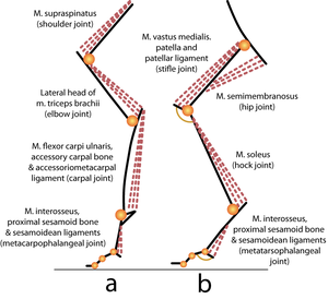
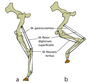
Some muscles have a high proportion of slow twitch fibres, using energy at a low rate. They are especially useful where a force slows down or movement prevention is required. This decelerating action requires relatively little energy, which is released as heat. The term "isometric", usually used to describe these fibres, is misleading, since this type of muscle action can take place while a muscle is being stretched, if the muscle is resisting stretch. This "braking" action of muscles occurs, for instance, in certain forelimb muscles when a horse lands from a jump (Fig. 6.2). Slow twitch muscle fibres usually predominate at sites where they are able to oppose the force of gravity, both in standing and moving animals, as in the example just given. In limbs, such postural muscles act over joints that would otherwise flex and cause the limb to collapse (Fig. 6.3).
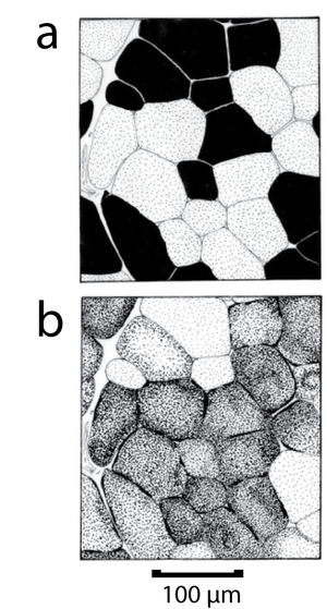
Fast twitch fibres differ from slow twitch fibres in several ways. Fast contraction demands fast control of the stimulating mechanisms with in the fast twitch fibre: thus there is more sarcoplasmic reticulum in these fibres. There is also an enzymatic difference in the rate at which myosin adenosine triphosphate (ATP) is split. Fast twitch fibres have a high activity, and slow twitch fibres have a low activity of the enzyme myosin adenosine triphosphatase (myosin ATPase). Fortunately for the easy study of the contraction speeds of different muscles, a histochemical method exists that differentiates between the two fibre types. This is because each fibre type has a different myosin isoenzyme, the difference in the enzyme activity of which is exaggerated at a high pH. By this means, fast and slow twitch fibres can be visualised in histological sections (Fig. 6.4).
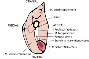
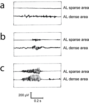
Muscles may have both propulsive and postural roles. Several muscles with broad attachments possess a high population density of slow twitch fibres nearest the pivot over which the muscle acts, and a high density of fast twitch fibres towards the periphery (Fig. 6.5). During standing or quiet walking, only the area of the semitendinosus muscle in which slow twitch fibres are dense is active (Fig. 6.6). The area dense in fast twitch fibres is recruited only during more violent activity. We have already discussed the mechanics of different areas of such a muscle (Fig. 5.4). The heterogeneity of fibre type distribution within a muscle may arise because of the necessity for fast twitch fibres to have a greater torque. Another advantage of this arrangement will be explained shortly.
- Fig 6.3 Limb posture
- Single joint muscles of the forelimb (a) and hindlimb (b) of a cat. The labels indicate the muscle, the osseous and tendinous structures assisting the postural function of the muscle, and the joint over which each muscle acts.
- Fig 6.4 Intrinsic speed and endurance of muscle fibres
- Transverse serial sections of the pig diaphragm, stained for myosin ATPase activity
- (a), a strong reaction indicating a high intrinsic speed of contraction, and succinate dehydrogenase activity.
- (b), a dense reaction indicating a high mitochondrial density and therefore high endurance. All slow twitch fibres have high endurance. Some fast twitch fibres have high endurance; others have low endurance. Single joint muscles form only a small part of limb muscle mass: most large muscles act over two joints
- Fig 6.5 Heterogeneous distribution of fibre types within a muscle
- Transverse section of the distal part of the thigh of a sheep, showing the variation in myosin ATPase low fibre population density within the semitendinosus muscle. The white region represents a density of 3 - 6%, mid pink area a density of 7 - 9%, while the dark pink area has 20 - 30% of all fibres within the region. Myosin ATPase low fibres, which depend entirely on an oxygen-supply for their metabolism, tend to lie closest to their blood-supply.
- Fig 6.6 Recruitment of fibres during various activities of a muscle
- Simultaneous electromyographic recordings from an area of the semitendinosus muscle of the sheep (Fig. 6.5) with a dense myosin ATPase low (AL) fibre population, and an area with a sparse AL fibre population density. In (a), the sheep is supporting weight on the limb, in (b) it is walking quietly and in (c) it is kicking violently.
Adaptations for speed
The speed with which a muscle can move a part of the body can be due to one or several of the following independent factors: 1.The rate of energy conversion within the fibres of the muscle, which affects the intrinsic speed of contraction of each sarcomere (Fig. 6.1). 2.The number of sarcomeres in series. When each sarcomere contracts simultaneously, the resultant effect is summation of the distance moved in unit time. A thin strap muscle therefore contracts, between origin and insertion, faster than a thick strap muscle or a pennate muscle of the same mass. 3.The angle of pennation, during a contraction (Fig. 5.7). 4.The skeletal attachments, which affects the torque of the muscle relative to the point of application of the force (Fig. 5.5).
Fibres specialised for endurance
There are only two characteristics of a single sarcomere of mechanical significance. The first is the intrinsic speed of contraction, already described. The second is the ability of the sarcomere to sustain a contraction during repetitive rapid stimulation, or tetanus. This ability has been called nonfatiguability, but might be better termed endurance. Endurance is directly dependent on the capacity of a sarcomere to derive energy by aerobic metabolism, whether from nutrients stored within the muscle fibre (intrinsic nutrients) or carried to the fibre in the blood (extrinsic nutrients).
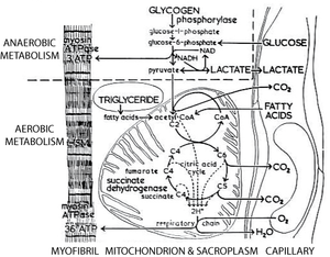
Thus a typical high endurance fibre is relatively small to allow for diffusion of oxygen and nutrients, has a rich blood supply, an intrinsic nutrient supply that must be burnt aerobically (triglyceride), a high density of mitochondria, a high activity of enzymes of the tricarboxylic acid cycle (Fig. 6.7) and a high density of oxygen carrying pigment (cytochromes and myoglobin). Because of this last property, high endurance fibres provide the colouring of red muscles, and are sometimes called red fibres.
- Fig 6.7 Aerobic and anaerobic metabolism in muscle
- The dotted line excludes the metabolic processes in muscle that use an extrinsic source of energy and oxygen, and that require the removal of metabolites from the muscle fibre. Under these circumstances, 3 moles of ATP are regenerated per mole of glucose consumed. In contrast, 36 moles are regenerated per mole of glucose metabolised through the citric acid cycle. The latter process is, however, effective only if an adequate blood supply is available. This cannot occur for all muscles during all periods of activity.
The relationship of endurance to function
Endurance is a property especially desirable in slow twitch, decelerating fibres. Muscles or parts of muscles predominantly postural in function are therefore aerobic and red. The part of the muscle closest to the blood supply often contains a predominance of slow twitch fibres (Fig. 6.5); the fibres using oxygen and blood born nutrients aggregate near their source of sustenance.
But not only slow twitch fibres are frequently used muscles and therefore need endurance. Well used muscles such as the diaphragm and the extrinsic ocular muscles contain large numbers of fast twitch, aerobic fibres. Also most muscles contain a significant proportion of these fibres, particularly in animals with the opportunity or necessity for plenty of exercise.
Intrinsic speed of contraction and endurance are separate properties and can vary independently within particular muscle fibres (Fig. 6.4). A fast twitch fibre that is used frequently will be aerobic; otherwise it does not need a rich blood supply. An anaerobic fibre can satisfy an occasional demand for sudden powerful movements by deriving energy from an intrinsic glycogen store. Anaerobic energy production is only about one-tenth as efficient as aerobic energy production (Fig. 6.7). It is useful only when a good blood supply is not possible; there is far more muacle in a body to be continually supplied aerobically. The subsequent build-up of lactic acid constitutes an "oxygen debt" that can only be "paid" during a rest period.
Endurance depends on muscle use
A characteristic of animals reared without normal muscle usage, for example pigs and broiler chickens, is an abundance of muscle fibres with low aerobic capacity and associated pigment. In domestic pigs the deep red part of M. semimembranosus, for example, contains a high proportion of aerobic fibres that are used for posture and quiet propulsion even in a closely confined animal. In contrast with the superficial fibres that are all too seldom used for propulsion, and are very pale. A similar comparison can be made with the red leg muscles and pale wing muscles of broiler chickens. Yet another example is the endurance of a hare that with its red musculature can lead a pack of hounds for an hour, and a rabbit that, with a sudden burst of energy, finds a burrow and time to repay the oxygen debt of its pale musculature. Athletic ability and its improvement by training are also related to an improved aerobic capacity of muscles along with an accompanying cardiovascular fitness.
Scaling effects on quadrupedal design
The problem of size
The size of structures is limited by their function. All mitochondria, and all muscle fibres, generally the same size, regardless of the mature body size of the animal in which they are found. But the femur of a mouse and a horse are greatly different in size. What functional limits are there to the sizes of various structures? Why is the femur of a small animal readily repairable, whereas a fracture in the femur of a horse cannot usually be treated? For an explanation, it is necessary to understand how the basic dimensions of length, area and volume vary with the size of an object, and what the significance of each to function is.
Isometry
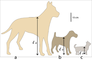
In Fig. 7.1 the length lb of an edge of cube b is twice the length la of an edge of cube a. The scale factor, f, relating a and b is 2. If instead of length, we compare areas, a face of cube b has 4 times the area of a face of cube a; the ratio of these areas is f2 = 4. And the volume of cube b is f3 = 8 times the volume of cube a. This result is true for any two similar shaped figures, regardless of their shape. Such figures are called isometric (Gr. isos, equal; metron, measure). Although even identical twins can virtually never be precisely isometric, in the natural world isometry is often a useful first approximation in the comparison of two organisms and their components. This can be true in a familiar example of different breeds of dogs.
Fig. 7.2 shows a Great Dane and a Fox Terrier, drawn to scale. The shape of their bodies is quite similar; their size difference differs by a scale factor f = 2. The ratio of two corresponding areas, such as the transverse sectional area of the semitendinosus muscle or the total surface area of the body, is f2 = 4. The ratio of two corresponding volumes, such as the volume of the thoracic cavity, the stomach or the left ventricle of the heart, is f3 = 8. The scale factor for the Great Dane and the Chihuahua is f = 4; in this case, corresponding areas have a ratio of f2 = 16 and volumes, a ratio of f3 = 64 between the two breeds.
- Fig 7.1 Isometric cubes
- An edge of cube (b) has twice the length of an edge of cube (a). The scale factor f = 2.
- Fig 7.2 Three approximately isometric breeds of dog
- Outline of a Great Dane (a), a Fox Terrier (b), and a Chihuahua (c). The height at the withers for each dog is = 80 cm, = 40 cm, = 20 cm. Therefore the scale factor for (a) and (b), and for (b) and (c) is f = 2; for (a) and (c) the scale factor f = 4.
The strength of the small
These geometrical relationships are important because some mechanical properties of the body depend on area, and some on volume. For example, since the overall density of animal tissues is similar, the weight of an animal depends on volume. The Fox Terrier weighs 6 kg. The Great Dane would therefore weigh 7 x f3 = 56 kg. We have argued that the strength of a muscle is proportional to the transverse sectional area of its fibres acting in parallel. Using the muscles of its forelimbs, neck and jaws, the Great Dane would therefore carry f2 = 4 times more weight in his mouth than the Fox Terrier. Relative to body weight, however, the Great Dane is weaker; his relative strength is f2/f3 = 1/f = 0.5 times that of the smaller dog.
Assuming isometry, the smaller an animal, the greater its relative strength. An ant can lift many times its own weight, not because it is differently constructed from a horse, but because it is smaller. In fact, a horse–sized animal constructed like an ant would be too weak even to left its legs.
Energy, speed and endurance of isometric animals
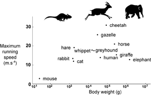
The assumption of isometry between animals enables us to make predictions. We have already stated that body weight should scale as f3, and that the strength of muscles, either singly or in total, will scale as f 102. But the work muscles can do (force x distance) is related to muscle mass (Chapter 5) and therefore scales as f3. Total body energy is therefore proportional to body mass M. During locomotion, this becomes converted to kinetic energy E: E = Mv2, where v is velocity. Both E and M scale as f3, v must therefore be a constant. Regardless of body size, isometric animals can propel their bodies at the same speed. Fig. 7.3 shows that this is to some extent true, for real animals.
During the hunt, what is the outcome of a tiny hare chased by larger hounds, chased in turn by even larger mounted huntsmen? The nutrient store of the body is also proportional to body mass. While maintaining maximum energy output, the time taken for nutritional exhaustion scales as f3, and since velocity is the same, the distance travelled before nutritional exhaustion scales as f3. The advantage of size is the ability to travel fast for longer. Small animals maintain prolonged activity only by continual nutritional replenishment. The size progression of hare, hound and horse must be reversed in terms of either athletic ability or cunning, if the hunt is to last long enough to be "sporting". Perhaps the only cunning the huntsman employs is to use the large nutritional stores of his horse!
- Fig 7.3 Top speed of mammals
- The cheetah, gazelles and antelopes are the fastest of all terrestrial animals. Another group of fast mammals include the horse, hound and hare. The slowest mammals include the mouse and elephant. In none of these groups does body size appear an advantage or a constraint to running speed.
Proportional and disproportional development
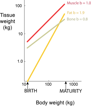
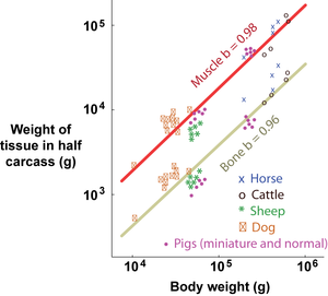
Isometry is a particular case of allometry (Gr. allos, other; metron, measure). Both terms relate to the measurement of the proportions of two components, or a component and the whole, during the development of an organism. Isometry refers to proportionate development, and allometry to disproportionate development. Development may be within a species, describing growth patterns (ontogenic allometry), or between species, describing evolutionary patterns (phylogenic allometry). Partly because body dimensions bear power functional relationships and partly because growth is a multiplicative process, it is convenient to study developmental patterns on logarithmic scales. When a double logarithmic linear relationship has a slope b=1, two weight components develop isometrically: when b < 1 or b > 1, they develop allometrically (Fig. 7.4).
- Fig 7.4 Relative growth of tissues in a beef carcass
- Total carcass muscle weight grows isometrically with body weight, since the slope of the regression on logarithmic scales, b, equals 1. For bone and fat, however, the slopes of the regressions lines are not equal to 1; bone grows slower and fat faster than the body as a whole.
- The values are for female Jersey cattle.
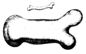
- Fig 7.5 Allometry of bones according to Galileo
- "To give a short example of what I mean, I once drew the shape of a bone, lengthened only three times, and then thickened in such proportion that it could function in its large animal relatively as the smaller bone serves the smaller animal; here are the pictures. You see how disproportionate the shape becomes in the enlarged bone. From this it is manifest that if one wished to maintain in an enormous giant those proportions of members that exist in an ordinary man, it would be necessary to find either much harder and more resistant material to form his bones, or else to allow his robustness to be proportionately weaker than in men of average stature; otherwise, growing to unreasonable height, he would be seen crushed by his own weight and fallen".
- Galileo Galilei: Discourses & Mathematical Demonstrations concerning Two New Sciences pertaining to Mechanics and Local Motions. 1638.
Allometry and scaling
Allometry is important mechanically if we recognise that developmental patterns in the musculoskeletal system arise because of scaling. Does a newborn animal differ in musculoskeletal proportions from an adult because of its size? Is a species of small size inevitably different in musculoskeletal proportions from a large maturing species? The scaling problem that has interested investigators since Galileo (Fig. 7.5) is that while body weight scales as f3, the structures supporting it scale as f2. Many have followed Galileo to the conclusion that larger animals compensate by developing disproportionately more massive limbs. However, Fig. 7.6 shows that a million-fold increase in body weight is insufficient to reveal a consistent change in the proportions of forelimb bones of quadrupeds. Neither is the change in shape of the bones of the pig during a nearly one hundredfold increase in body weight from birth to maturity consistent with the idea of more massive skeletons in heavier animals (Fig. 7.7).
Postnatally, the proportion of bone in the body declines (Figs. 7.4 and 7.8). Apparently, an immature animal needs a greater proportion of its body as bone because growing bone is less mineralised. Bone mineral, however, maintains a constant proportion of carcass weight (Fig. 7.8). Muscle tissue, forming approximately 40% of the body mass, is too large a proportion of body mass to adapt by increasing this proportion. To scale with the same static muscle strength as a mouse, an elephant would need to be almost 100% muscle! In fact real mammals of different size, within and between species, have approximately the same muscularity (Figs. 7.4, 7.8 and 7.9).
- Fig 7.6 Bone proportions in terrestrial quadrupeds
- Animals can vary in size with no apparent necessity for changes in skeletal proportions.
- Fig 7.7 Postnatal change in shape of the radius and ulna of the pig
- The bones are drawn to the same length. Unossifiied regions of the immature bones are shown blue-grey. There is no apparent requirement for the bone in the adult to be more massive than that in the neonate.
- Fig 7.8 Postnatal growth of muscle and bone in the pig
- During a hundred-fold increase in carcass weight, from which the variable effect of adipose tissue has been removed, total muscle and the mineral content of the limb bones grow proportionately. "Bone", which here includes periosteal, cartilage and medullary tissues, comprises a greater proportion of the carcass in the immature animal than in the adult.
- Fig 7.9 Muscle and bone proportions in mature animals of different size
- There is no apparent need for animals differing in size as much as do dogs and horses, to support and propel themselves using a different proportion of muscle and bone in their bodies.
- Fig 7.10 The effect of body size on histochemical fibre type populations
- A schematic representation of the relative density of the myosin in ATPase low fibre type of fibre, as observed in transverse sections of the semitendinosus muscle of seven species of mammals. The density in the deep part of the muscle, as well as the extent throughout the muscle, of myosin ATPase low fibres increases with increasing size of the animal.
The design of limbs
Axes of joint movement
The skeleton of each limb is divided into movable segments. Movement is possible because of the presence of synovial joints between each segment. Restrictions are placed on the actions of different joints so that they act in different ways. These restrictions are:
- 1. The shape of the joint surfaces.
- 2. The ligaments surrounding the joint (for example a hinge joint will have ligaments that restrict the movement to only one plane).
- 3. The ranges of contraction of muscles, (for example, dorsal flexion of the metacarpo-phalangeal joint is restricted by the interosseous muscle or interosseous ligament as in Fig. 2.16).
- 4. The shape of the limb (for example, flexion of the stifle is restricted by contact of the crus with the thigh).
For each joint, there are four possible axes of movement, each affected to varying extents by the above restrictions. These are:
- 1. Flexion – extension; a change of angle in a sagittal plane (hinge joint)
- 2. Adduction – abduction; a change of angle in a transverse plane
- 3. Rotation; movement around the axis of the limb; and
- 4. Gliding; movement without change of angle, in a plane transverse to the axis of the limb.
Combinations of these movements are usual, but it is convenient to consider each one separately.
Patterns of limb joint movement
The possible movements in the corresponding joints between the forelimb and hindlimb have some similarities between the different limb segments:
| Forelimb | Hindlimb | Axes of movement |
|---|---|---|
| Shoulder | Hip | Flexion-extension; Adduction-abduction; Rotation |
| Elbow | Stifle | Flexion-extension; Rotation |
| Carpus | Tarsus | Flexion-extension |
| Metacarpophalangeal | Metatarsophalangeal | Flexion-extension |
| Interphalangeal | Interphalangeal | Flexion-extension |
The axes of movement thus become more restricted distally. A limb can be regarded as an extensible rod, rather freely moveable about the shoulder and hip joints, and extensible because flexion and extension are possible in all joints, in an alternating pattern distally as far as the metacarpophalangeal joints (Fig. 8.1). Proximally, the more complex movements are matched by the complexity of the muscles surrounding these joints.
- Fig 8.1 Flexion and extension of the limbs of the horse during the gallop
- Note the extreme flexion of joints distal to the stifle and elbow during protraction, the interdependence of stifle and hock movement, and that the flexion position differs markedly between forelimb and hindlimb.
Limbs as struts
The trunk of the quadruped is supported on four struts. If static support of the trunk were their only function, these struts would be straight. Flexion of the joints of the limb results in a torque exerted by gravity on each joint (Fig 6.3). Larger mammals, for example the giraffe and the elephant (Fig. 8.2) stand with straight limbs to minimise this torque; smaller animals are able to oppose the torque more easily with muscular force. Recall that the smaller animal is relatively stronger (Chapter 7).
Each joint of the strut needs a mechanism to prevent flexion, especially in large animals like a horse in which a “stay apparatus” is defined; each joint is supported against gravity by a ligamentous or an extremely pennate arrangement of muscles (Fig. 5.8). Denervation of any of the muscles shown in Fig. 6.3 would reduce the animal's ability to bear weight on the limb. Each of these muscles has been chosen deliberately because it acts over only one joint. This single-joint muscle system is assisted and sometimes superseded by a two-joint muscle system to be described later in this chapter.
- Fig 8.2 Size effects on mammalian skeletons
- The torque exerted by gravity about the limb joints is reduced in the larger species by increasing the angles of flexion.
- These animals also show a feature of the vertebral column discussed in Chapter 9. The cat (c) and the rat (d) have cranially directed vertebral spines in the caudal series, with the tenth and twelfth thoracic vertebrae, respectively, anticlinal. The bending imposed on the vertebral column of the elephant (a) and the giraffe (b) necessitates caudally directed lumbar vertebral spines.
How each limb is attached to the trunk
The most stable quadrupedal posture results from splaying the limbs. However, even in giraffes the attachments of the limbs to the trunk are so designed that they can maintain the basically unstable equilibrium of a heavy load supported on nearly vertical piles. In the hindlimb, the proximal segment of the limb, the hip bone, is fused to the vertebral column and to the contralateral segment (Fig. 8.3 a). The effective postural attachment for the hindlimb is therefore the hip joint. This spherical joint allows flexion–extension, adduction–abduction and rotation freely. Postural control is therefore dependent on muscles fixing the joint, particularly to prevent abduction and flexion. That muscles are necessary for the stabilisation of the hip is evident when you see a weakened cow trying to stand on smooth concrete.
The proximal segment of the forelimb, the scapula, has no direct bony attachment to the vertebral column. Posture is maintained by the transmission of the gravitational force not through bone, but through the muscle fibres of m. serratus ventralis, which carries the trunk between the two forelimb struts as a sling (Fig. 8.3 b). Since there is no bony joint, all axes of movement are possible, and all extrinsic muscles of the forelimb are needed to stabilise the attachment of the prop. In the transverse plane, in particular mm rhomboideus and trapezius act as abductors and m. pectoralis superficialis acts as an adductor of the limb.
- Fig 8.3 Pivots for the limbs of the dog
- Cranial view of the articulations between the pelvic girdle (a) and the pectoral girdle (b). The level of each pivot is shown with arrows. Detachment of the scapula from a bony connection with the trunk raises the pivot to the level of entry of nerves and blood vessels to the limb.
Limbs as pendulums
The important movements of each limb as a whole are:
- a.Flexion and extension, to alter the length of the limb (Fig. 8.1).
- b.Protraction and retraction, in which the limb swings cranially and caudally, respectively, in a sagittal plane (Fig. 8.4).
- c.Adduction and abduction, in a transverse plane, which Fig 8.3 suggests must occur in the hindlimb at the hip and in the forelimb at the shoulder or between the forelimb and the trunk.
The main movement for propulsion is protraction—retraction. It is useful to regard each limb as a pendulum, swinging in a sagittal plane. During slow locomotion, the pivot for the hindlimb is the hip joint (Fig 8.4 a). For the forelimb, the pivot is not the shoulder, but is more proximal (Figs 5.3, 8.3 b, 8.4 b).
- Fig 8.4 Limb movements of a walking cat
- 1 Foot leaves ground.
- 1-2 Protraction, or swing phase. Slight initial flexion of stifle, hock and elbow. Hip and shoulder elevate slightly.
- 2. Foot contacts ground. Stifle, hock and elbow are extending.
- 2-1 Retraction, or stance phase. Stifle, hock and elbow continue extending. Hip and shoulder are lowered slightly.
The movements of the joints of each limb are small compared with the movements of the limb as a whole. The movement during walking is therefore best described as that of a pendulum with a pivot at the hip for the hindlimb. The pivot for the forelimb, however, lies proximally to the shoulder joint.
The effect of size on pendulums
If a pendulum swings at its natural frequency of oscillation, this frequency is inversely proportional to the square root of its length. We presume that at the natural frequency of oscillation, propulsion will involve the least effort. Natural frequency therefore scales as f–1/2. The distance moved by the tip of the pendulum at each swing, the stride length, scales as f; this distance multiplied by frequency is the speed of the animal and therefore scales as f–1/2.f = f1/2. We conclude that if a dog and a horse, with a scale factor of 4, are walking at an easy speed, the horse walks only twice as fast as the dog. This does not, of course, contradict the idea that dogs and horses have a rather similar maximum speed of running (Fig. 7.3).
Improvements to pendulum design
If the natural frequency of oscillation of the pendulum involves least effort, it is advantageous to make this frequency as high as possible while maintaining limb length as long as possible so as not to reduce stride length. This is achieved in four ways. The centre of gravity of the limb is made as proximal as possible (Fig. 8.5 b). First, the bellies of muscles operating distal joints should lie close to the pivot, transmitting their force by means of long tendons. This is made easier if propulsive muscles operate mainly about the pivot, rather than by bending the limb distally. Fig. 8.4 shows that in walking, the limb is indeed an almost rigid pendulum. If distal joints have fewer axes of movement than proximal joints, the tendinous control apparatus is much simplified. We saw earlier in this chapter that this is the case. Also, the muscles responsible for fixing each joint lie proximally to the joint (Fig. 6.3). An additional advantage of having muscles located proximally is that they are then closer to the heart, thus reducing the length of the vascular channels and thereby improving the efficiency of the blood supply. Secondly, the structures forming a friction contact with the ground must be light, whether they be naturally grown keratin, or metal shoes. The ungulate (hooved animal) evolved for this reason.
Thirdly, the number of digits can be reduced, effectively to two in many artiodactyls (even toed ungulates) and to one in some perissodactyls (odd toed ungulates). A single structure is stronger than a paired structure of the same weight and length. Thus even in artiodactyls, fusion of the metapodial segment often occurs. Such a reduction in digits enhances cursorial (Latin: cursor, runner) ability and sacrifices the ability to use hands for specialised procedures.
- Fig 8.5 Improvements to pendulum design
- Modifications to a basic pendulum (a) that increase the natural frequency of oscillation (b, e) or the distance moved by the tip in each swing (c, d).
- Fig 8.6 Phylogenetic elongation of the distal end of the mammalian limb
- Comparison of the hind limb of the bear (a), dog (b) and deer (c) shows both a progressive elongation of the distal segments of the limb and a progressive incorporation of the distal segments into the limb pendulum from the plantigrade (a) to the digitigrade (b) and unguligrade (c) stance, as the limb becomes cursorily adapted.
Balancing the pendulum
The distal limb segments should be as long as possible (Fig. 8.5 c). This is achieved either by actual elongation of the distal segments relative to the proximal segments (Figs. 8.2 and 8.6), or by incorporation of the distal segments into the pendulum by running on the tip of the toes (Fig. 8.6).
The pivot of the pendulum should be as proximal as possible (Fig. 8.5 d). Some mammals have a complete bony pectoral girdle, which compels the forelimb to pivot from the shoulder joint (Fig. 8.7 a). A cursorial adaptation has been the reduction of bony elements of the pectoral girdle, freeing the scapula and allowing the limb to pivot from a point proximal to the shoulder (Figs. 5.3, 8.3 b, 8.4 b, 8.7 b). The dorsal border of the scapula moves cranially in limb retraction (Fig. 5.3). This enables muscles connecting the scapula to the head and neck (Mm rhomboideus, trapezius and serratus ventralis), and movements of the neck, to assist retraction. In galloping, in which the footfalls of the forelimb closely follow one another, the head is lowered during retraction and raised during protraction.
The pivot is moved into the vertebral column in animals that gallop with a flexible column. This applies to forelimbs and hindlimbs, and not only elongates the pendulum but enables axial muscles to participate in propulsion (Fig. 5.3).
- Fig 8.7 Adaptation of the pectoral girdle in a cursorial mammal
- In the echidna (a), the clavicle and the coracoid form two complete bony bridges between the scapula and the sternum. In the dog (b), only remnants of these bridges remain, represented by the coracoid process of the scapula and a fibrous or occasionally ossified tendinous intersection within the brachiocephalicus muscle. The pivot for the forelimb can be located proximally to the shoulder.
Reciprocating the pendulum
The pendulum should be long in retraction, but short in protraction (Fig. 8.5 e). At slow speeds, it is no advantage to shorten the protracting limb since the limb swings at a natural, low frequency (Fig. 8.4). At fast speeds, the protracting limb is flexed as much as possible (Fig. 8.1).
Short and longheaded muscles
Over most joints, there are muscles with actions limited to a particular single joint, as in Fig. 6.3, and other muscles that, in addition, act over adjacent joints (Fig. 8.8). It is convenient to call muscles acting over a single joint "shortheaded", and muscles acting over more than one joint, "longheaded". This nomenclature concurs with, for instance, that used for the long head of M. triceps brachii, as well as the short and long digital extensor muscles of the hindlimb.
- Fig 8.8 Short and longheaded muscles
- The pairs of counteractive muscles shown in the hindlimb of the dog (a) are m. rectus femoris and m. semitendinosus, as longheaded muscles, and m. vastus lateralis and m. adductor as shortheaded muscles. Muscle lengths are compared between the flexed hip and stifle position (b) and the extended position (c). The longheaded muscles tend to maintain a constant length over a natural range of limb function.
A severe restriction on muscle function: active insufficiency
There is a problem associated with shortheaded muscles that is fundamental to the design of limbs. For any muscle, there is only one stage at which the force is maximal over the whole range over which the muscle contracts (Fig. 4.4). A shortheaded muscle is therefore properly effective at only one angle of the joint over which it acts. A muscle is therefore insufficient because of the way its contractile mechanism works. A muscle with its sarcomeres at any length other than near 2.2 µm is said to be actively insufficient.
- Fig 8.9 The contribution of a longheaded muscle to the standing jump of the cat
- The semitendinosus muscle (dashed outline) has the same length when the hindlimb is in the fully flexed position as it does with the limb in the fully extended position. This muscle therefore assists hip extension without changing from its optimal length. It is able to do this only by the counteractive action of stifle extensors.
“Antagonism” and “Counter activity”
This naturally creates a problem in the design of limbs. The propulsive thrust, as well as the resistance to gravitational force, should be optimal over a whole range of joint angles, if the system is to be useful under a variety of positions and circumstances. The solution to the problem is found in the presence of longheaded muscles, of which there are many in both fore and hindlimbs. The so–called “antagonistic” muscles, M. rectus femoris and M. semitendinosus give an example. They are usually called "antagonistic" because they have opposite effects on the hip and stifle joints (Fig. 8.8). However, because the hip and stifle often flex and extend together (Fig. 8.9), such longheaded muscles appear to act together to a common purpose, rather than antagonistically. The term "counteractive", implying neutralisation of effect rather than opposition, is therefore more appropriate.
So muscles work without changing length!
The angles of the hip and stifle in Fig. 8.8 represent the fully flexed (b) and extended (c) position of the dog's hindlimb. The lengths of the two longheaded muscles have changed less than the shortheaded muscles. It seems possible, then, that limbs move while many of their muscles remain at optimal length for force production. This is borne out in Fig. 8.9, in which it appears that the caudal thigh muscles of the cat can propel the whole body into the air without change of length. In order to resolve this apparent contradiction, perhaps one should consider that counteractive longheaded muscles make small contractions alternately, like sliding ratchets. Limbs, with their array of linear motors, work as hard as a kind of machine that humans have not yet got round to inventing!
Reciprocating joints
Such a mechanism should also be able to solve a similar problem as the limbs support the weight of the standing animal, providing again that the angles of the hip and stifle are fixed in relation to one another. The shorter the range of contraction of the muscles in a longheaded muscle system, as would occur by an increasing degree of pennation, the more interdependent would be the movement of the two joints. In an extreme case, the muscles are ligamentous, and the movement of one joint cannot occur without movement of the other. A clinically relevant example is the M. fibularis tertius of the horse (Fig. 8.10). Being entirely tendinous, hock flexion must follow stifle flexion obligatorily, unless M. fibularis tertius has been ruptured by injury. Because the ranges of contraction of the counteractive M. gastrocnemius and M. flexor digitorum superficialis are small, stifle fixation in the horse results in almost complete fixation of the hock, and stifle and hock movements are almost totally interdependent (Fig. 8.1). Such an arrangement has been called a “reciprocal apparatus”, and is an important part of the stay apparatus in large animals.
A severe restriction on limb function: passive insufficiency
Even when a longheaded muscle is a strap muscle and has the longest range of contraction possible (44% of fully stretched length: see Fig. 4.3), it is not possible to allow for full independent movement of both the joints it acts over. Thus when the hip of any quadruped, and also any but the most limber human, is fully flexed, the stifle cannot be fully extended. In this case, the semitendinosus muscle is insufficient but for a different reason to that for the actively insufficient shortheaded muscle described above. Longheaded muscles are intrinsically passively insufficient, especially so when they are highly pennate.
- Fig 8.10 Ligamentous adaptations of longhead muscles
- M. fibularis of the horse is entirely ligamentous. Stifle flexion (b) therefore produces hock flexion automatically, and M. gastrocnemius is kept at optimal length. The action of M. flexor digitorum superficialis also ensures that stifle extension (a) is also accompanied by hock extension. The position of the limb in (a) and (b) represent the retraction and protraction phases of a fast gallop as in Fig. 8.1.
Limbs are controlled proximally by key joints and nerves
At the expense of joint independence, muscles in the brachial and femoral regions control much of the action of limbs. This is true even for the interdigital joints, since the digital flexors and extensors are longheaded muscles that arise, by no accident, proximally to the elbow and stifle. The control of elbow and stifle fixation and movement is critical for all the more distal joints. The elbow and stifle joints have therefore been appropriately called key joints of the limbs. The nerves innervating muscles fixing these two joints are therefore key nerves.
Using short- and long-headed muscles together
Animals in which stifle and hock action are less interdependent need a shortheaded muscle to fix the hock. This is the m. soleus (Fig. 6.2 b), often used as a model of a muscle with a high proportion of slow twitch, decelerating fibres. Well developed in the cat but absent in the dog, one can deduce that m. soleus frees the cat's hind limb from a merely postural and cursorial function for such activities as tree climbing. M. soleus becomes less significant, or absent, in the larger animals with limbs functioning only for weight bearing and running.
Having considered several aspects of how the limbs are attached to the trunk and how each limb, on its own, contributes to postural and locomotion, we now begin to investigate the mechanics of the whole animal.
A safely factor limits how fast limbs can move
The problem is resolved if we accept that the total quantity of bone and muscle in an animal is related to dynamic rather than static function. For bone, the ability to absorb energy of impact during locomotion is much more critical than the ability to support a static load. This energy absorption ability is proportional to mass and scales as f3. If bones bore only static loads, it is the mouse, as it exists, that has the massive skeleton relative to the horse! For muscle, the rate of energy production is more critical than static strength. We have seen that maximum velocity is constant, regardless of body size (Fig 7.3). The limb movements of large animals must therefore be relatively slow. Supposing that a dog and a horse scale linearly at f=4, and run at the same speed, stride frequency, and hence the intrinsic speed of contraction of the muscles accelerating the limbs, is slower in the horse, scaling as 1/f = 1/4. The muscles of the large animal contract at a slower rate. It would be very dangerous for the horse if the limbs had the same stride frequency as the dog. Indeed large animals have a higher proportion of slow twitch fibres than smaller species (Fig. 7.10).
There is a safety factor that limits the rate of limb movement in larger animals. In order to support static loads, both the tissues supporting the animal, and the tissues propelling it, have no need for disproportionate development.
The design of the vertebral trunk
The trunk is a horizontal beam
The body of the dog shown in Fig. 9.1 a is represented mechanically by a beam, the vertebral column A–D, 45 cm long with a uniformly distributed load of 0.2 kg.cm–2 (the neck and trunk), and a concentrated load cranially of 2 kg (the head). The total weight is therefore 11 kg. With the fore and hindlimbs each represented each by one simple strut and placed as shown at B and C, the opposing reaction forces can be calculated as 7.9 kg for the forelimbs and 3.1 kg for the hindlimbs. This turns out to be approximately the situation in a real dog in which the weight borne by the forelimb is about twice that borne by the hindlimb. Since the weight of the hindlimb of the dog is about the same as that of the forelimb, one must conclude that the weight of hindlimb in excess of what is needed for postural support is available for propulsion; in other words the forelimb and the hindlimb of the dog differ in their postural and propulsive roles. The forelimb supports and balances, the hindlimb pushes.
In Fig. 9.1c, muscles preventing bending include (a) the epaxial muscles of the neck and thorax, (b) the hypaxial muscles of the thorax, and (c), the hypaxial muscles of the lumbar region. Props assisting the action of these muscles and the ligaments shown are (p) the spinous process of the axis, (q) the spinous process of the first thoracic vertebra (together with adjacent spinous processes), (r) the spinous process of the anticlinal vertebra (eleventh thoracic), (s) the sacrum and (t) the costal arch. (u) and (v) are the forelimb and hindlimb respectively. Note that the shape of the vertebral column is opposite to that of the bending moments shown in Fig. 9.1b for the horizontal beam A — D.
- Fig 9.1 Bending in the vertebral column
- The trunk of a dog is represented in Fig. 9.1a by a horizontal beam A — D, 45 cm long with a uniformly distributed load of 0.2 kg.cm-1, together with a concentrated load cranially of 2 kg (the head). The total weight is 11 kg. With the limbs placed as shown, the opposing reaction forces are 7.9 kg in the forelimb and 3.1 kg in the hindlimb. Bending moments along the vertebral column are shown graphically in Fig. 9.1b.
Forces along the beam
The skeleton of the trunk is a row of separate bones, the vertebral column, on its own hardly a stable bridge. Its rigidity is maintained to a large extent by a compressive force produced in the massive muscle surrounding the column (Fig. 9.2). As a bridge, therefore, this structure is comparable to prestressed concrete. We have already seen that the trabecular network is oriented axially within the vertebral bodies, to resist the tensile stress (Fig. 3.2). When the axial muscles are relaxed as during anesthesia, the vertebral column is no longer rigid. Rigidity of the vertebral column is attained also by the supraspinous and dorsal and ventral longitudinal ligaments (Figs. 9.2 and 9.3) and by the shape of the synovial intervertebral (zygapophyseal) joints.
- Fig 9.2 Transverse section of a pig at the thoracolumbar junction
- Caudal aspect, showing the intervertebral joint and the structures supporting the vertebral column.
The effect of gravity on the beam
Opposing this rigidity are bending moments that are a parabolic function of x, the distance in cm from A along the horizontal beam, and can be calculated for any value of x (Fig. 9.1 b). The bending moment in a ventrally concave sense is maximal at B, and the bending in a dorsally concave sense is maximal at about two-thirds the distance between B and C. The beam is subjected to no bending at two points between B and C. At some points, bending is not as much a problem as it is in others. This is compensated for in several ways, depending on the location.
Improving the beam with good engineering
Bending in a ventrally concave sense is opposed by first altering the shape of the beam to produce a dorsally concave curve at B (Fig. 9.1 c), and secondly by providing a system of struts, the spinous processes of the cervical and thoracic vertebrae at B and the sacrum at C, with stays, the nuchal ligament and the dorsal muscles of the neck at B and the sacro-tuberous ligament at C. Bending in a dorsally concave sense is opposed again by altering the shape of the beam, by providing a ventrally concave curve in the thoracolumbar region, and a series of struts, the costal arch, with stays, the ventral thoracic and abdominal muscles.
Inclined spinous processes
We can tell the direction of the forces on the spinous processes of the vertebrae by the way they lean, as you can easily tell in which direction the contestants in a tug-of-war are pulling, and resisting being pulled. Mechanical struts are more effective when a force is applied to them at an acute angle rather than a right angle. Therefore, the tall spines of the cranial thoracic vertebrae slope caudally. In the cat, this occurs as far caudally as the tenth thoracic vertebrae (Fig. 8.2), and the eleventh in the dog (Fig. 9.1 c).
- Fig 9.3 Median section of an intervertebral joint in the thoracic region
- Structures are shown which resist bending or hydrostatically distribute a uniform compression stress on the vertebral bodies.
Flexibility of the vertebral column
Apart from the joint between the first two cervical vertebrae, the intervertebral joints are not synovial joints. It is important that joints in a column under compression should be able to distribute pressure evenly over the opposing surfaces of the vertebral bodies, regardless of the angle of the joint. Intervertebral movement and even pressure distribution are achieved hydrostatically by the nucleus pulposus between each body (Figs. 9.2, 9.3). The change in shape of this mucoprotein gel with movement of the joint is accommodated by the annulus fibrosis, a lamellar arrangement of collagen fibres. The lamellae pass from vertebra to vertebra with their fibres crossing each other obliquely. They are therefore constructed to withstand the tensile stress imposed by the bending of the vertebral column, and also to prevent rupture of the nucleus pulposus. The mechanical and morphological concept suggested by the term intervertebral disc is misleading.
This rigid beam can be flexible
In the dog, the maximum movement occurs between the segments around the tenth and the eleventh thoracic vertebrae. These segments are the most vulnerable to the injury of intervertebral structures. This is especially so in dogs with short legs which must use their vertebral column to a greater extent for propulsion than long legged dogs. The flexibility of the vertebral column varies between species. A galloping horse maintains an almost rigid back (Fig. 9.4 a). This is also true for some of the fastest terrestrial animals, the gazelles and antelopes, some of which are small (Fig. 9.4 b). This is in contrast with the cheetah (Fig. 9.4 c). The big cats, which have flexible vertebral columns, spend little of their time standing, as compared with herbivores of equivalent size, which have more rigid columns. The axial muscles of herbivores are presumably more postural in function than those of carnivores and the smaller animals.
- Fig 9.4 Flexibility of the vertebral column in galloping animals
- The diagrams on the left represent full extension and the right side, full flexion of the vertebral column. The horse (a) and the gazelle (b) do not flex their backs appreciably, in contrast with the cheetah, (c).
The vertebral column in locomotion
The locomotory apparatus of the trunk is driven by the caudal epaxial muscles, notably the longissimus muscle (Fig. 9.2) and its attachments. In the species in which the apparatus is well developed, such as rodents, felids and canids, the attachments of the longissimus muscle to the spinous and transverse processes of the caudal thoracic and lumbar vertebrae are functionally strengthened by an angling of these processes away from the direction of tension. Thus, the transverse processes of the lumbar vertebrae slope cranially and ventrally. For the spinous processes, the effect is opposite to that seen in the cranial segments of the vertebral column where they slope caudally against the tension in the dorsal stays of the cervicothoracic region (Fig. 9.1 c). There is therefore an anticlinal vertebra, which represents the changing point (Fig. 8.2). In species that presumably do not use their vertebral column effectively to lengthen the hindlimb pendulum in locomotion, an anticlinal vertebra is absent.
We can now proceed to consider the action of the trunk and limbs as used by quadrupeds in performing usual tasks.
Locomotion
The standing quadruped
The location of the centre of gravity of a horse is shown in Fig. 10.1. In the horse, 55% of the weight of the body is supported by the forelimbs and 45% by the hindlimbs. A horse usually rests one hindlimb while standing, but can do so for a forelimb only with difficulty. Relatively more weight is presumably supported by the forelimb of the bison and by the hindlimb of the rabbit (Fig. 10.2). The dog carries two thirds of its weight on its forelimbs and one third on its hindlimbs (Fig. 9.1).
- Fig 10.1 Location of the centre of gravity of a horse
- This is found in a transverse plane immediately caudal to the xiphoid process, and in a dorsal plane between the ventral and middle thirds of the trunk.
- Fig 10.2 Species differences in the location of the centre of gravity
- Compare these probable locations in the bison (a) and rabbit (b) with that determined for the horse in Fig. 10.1.
Using the head to change the centre of gravity
The function of the limbs as struts in supporting the trunk, and the function of the trunk as a supporting beam, have already been discussed. The remaining major bulk of the body, the head and neck, is also important in the standing quadruped because of its influence on the centre of gravity. Raising the head will bring it nearer to the trunk in the dorsal plane, and lowering it to bring the neck parallel to the trunk axis will increase this distance. Thus raising the head moves the centre of gravity caudally, removing weight from the forelimbs, and lowering it moves the centre of gravity cranially, increasing weight on the forelimbs (Fig. 10.3). Thus when a lame forelimb takes weight, the head is raised to relieve it. When one wishes to lift a forefoot of a horse or ox, its head should be raised and move laterally away from the foot to be lifted. On the other hand, it should be lowered with a hindfoot is to be lifted. An animal can be prevented from kicking with its hindlimb by holding its head high.
- Fig 10.3 Use of the head and neck to alter the centre of gravity
- The horse can lift a forefoot when the head is raised (a), and a hindfoot when the head is lowered.
- Fig 10.4 Curvature of the vertebral column in the sitting cat
- The shape of the thoracic cage (doted outline) is maintained by bending the vertebral column predominantly near the thoracolumbar junction.
Motion without change of location
The natural manner in which each species moves into a sitting or lying position and back to a standing position should be observed in normal animals. Assistance to animals incapacitated by disease or narcosis should be given in such a way as to enable the animal to complete its task in its natural manner.
Sitting down: Only animals with a vertebral column flexible enough normally adopt a sitting position. It is a usual position for the dog and cat (Fig. 10.4), an occasional one for the pig, and a possible although a very unusual one for cattle.
Lying down: From the standing position, the dog, cat and pig adopt a sitting position first. They lie in ventral recumbency with all four limbs tucked underneath or the hindlimbs placed to one side. Cattle and sheep first raise their head to shift the centre of gravity caudally, and then flex their carpal joints one after the other while bringing the centre of gravity cranially by lowering the head. The cranial part of the trunk is now supported with the carpal joints on the ground. The hindlimbs are now placed as far as possible under the trunk, and the caudal part of the trunk is dropped to the ground with the hindlimbs to one side. Finally, the carpal joints and elbows are flexed to lower the sternum to the ground. The horse arches its back, brings its four limbs underneath the trunk, lowers its head, flexes its limbs and drops heavily to one side.
Standing up: The smaller the animal, the more easily it can spring to its feet with a sudden back movement, but even horses can manage to do this. A slower, more deliberate movement is, for the dog, cat and pig, essentially the reverse process of lying down. Cattle and sheep raise themselves up on to their hindlimbs first, then on to their flexed carpuses. The horse rolls its trunk to sternal recumbency, collects its four legs underneath, and then protracts and extends its forelimbs, raising its cranial trunk before its caudal trunk, by pushing its weight over its forelimbs with a thrust from the hindlimbs.
Standing on hindlimbs: In order to achieve this, the centre of gravity must lie vertically above the hindfeet (Fig. 10.5 a, b). This is easier for horses than cattle. Horses can prance and kick with their forelimbs, but cattle cannot. A copulating bull can maintain the position only briefly, and uses the cow for support. Standing on hindlimbs is especially easy for animals with a more caudally located centre of gravity (Fig. 10.2 b).
- Fig 10.5 Stable positions for the horse on its hindlimbs
- Both in rearing (a) and in the levade (b), the centre of gravity of the horse lies over the hindfeet.
- Fig 10.6 Propulsion and friction forces
- The insertion of a plate between the hose and the ground enables the forces acting on the body during a propulsive movement of the hindlimbs during the gallop to be visualised.
Propulsive force
A propulsive force, applied to the limb to retract it, propels the animal over the ground. Opposing the propulsive force is friction force, acting between the animal body and the ground. It is the friction force that acts in the direction of movement. This is best visualised by interposing a plate between the animal and the ground (Fig. 10.6). When there is no friction between the plate and the ground, the propulsive force accelerates the plate and not the animal body. If the friction force equals the propulsion force, the plate remains at rest, and the animal is accelerated. Friction, which is usually thought to oppose motion, is essential for locomotion. The construction of the surface contact with the ground is vitally important and is often a source of breakdown in running animals, just as it is for motor vehicles.
In animals that use their vertebral column in running, the fore and hindlimb pendulums swing about a pivot near the thoracolumbar junction (Fig. 10.7). Axial muscles and extrinsic limb muscles acting over this pivot produce the propulsive thrust.
- Fig 10.7 The propulsive apparatus of the greyhound
- (a) Hindlimb. Retraction is brought about by the extensors of the vertebral column (x, m. longissimus and its dorsal aponeurosis) and the extensors of the hip (y, the middle gluteal muscle and z, the caudal thigh muscles).
- (b) Forelimb. Retraction is brought about by the flexors of the vertebral column (w, the external abdominal oblique muscle and x, rectus abdominis), and suitably placed muscles of the forelimb (y, latissimus dorsi and z, the deep pectoral muscle).
Gaits
Any continued movement of a quadruped over the ground necessitates a pattern of limb movement. Such a pattern is called a gait. There are obviously many possible ways of moving four limbs in relation to one another. Several of these may be exploited by a single species, and quadrupeds use many different gaits as a whole. When it is realised that 27 gait formulas have been recorded for the walk of the horse, and that this is not the only gait used by this species, the complexity of this subject is apparent. This account is limited to a description of the simple extremes of gait types, in the belief that these can be used to interpret the locomotory patterns of animals in real situations.
Symmetrical gaits
In considering a pair of forelimbs or hindlimbs, the sequence of footfalls may be symmetrical, that is, the interval between footfalls of right and left feet, and left and right feet, is the same. A human in normal walking uses such a symmetrical gait. Alternatively, the sequence of footfalls may be asymmetrical; the interval between footfalls of right and left feet, and left and right feet, is unequal. A child while “skipping” uses such an asymmetrical gait.
Symmetrical gaits of quadrupeds include the walk, trot, and pace. Asymmetrical gaits include the various types of gallop.
The slow walk
For one limb to be lifted slowly, the centre of gravity must lie within a triangle formed by the remaining three feet (Fig. 10.8). The most stable form of progression will therefore have three feet on the ground at any one time, and the centre of gravity shifts with the limb movement. The animal can stop at any instant without falling over. In animals in which the centre of gravity lies cranial to the transverse plane midway between the fore and hindlimbs, (Figs. 10.1 and 10.2 a), either hindlimb can be lifted without lateral change in the centre of gravity. However, such lateral movement is necessary to lift the forelimbs, and will be assisted by alternating movements of the head, neck and trunk (Fig. 10.9).
All animals use the slow walk at times when stability is important, for example when walking over rough terrain and by animals bearing awkward loads. It is visualised by a gait diagram in Fig. 10.10 a.
- Fig 10.8 Support triangles
- When a horse stands on all four feet, its centre of gravity lies as shown diagrammatically in dorsal view (a), cranial to the diagonals between the feet. Either hindfoot can now be lifted without change in weight distribution, because the centre of gravity lies within the triangle of support formed by the other three feet (b, c). Raising the head as in Fig.10.3 a directs the centre of gravity caudally. In (d), either forefoot can now be lifted. The centre of gravity need not be directed so far caudally if the head deviates to the side; if it deviates to the left, the right forefoot can be lifted (e).
- Fig 10.9 Head, neck, trunk and tail movements during the slow walk
- If protraction of the left hind limb in (a) produces the axial displacement shown in (b), the left forefoot can be lifted and the limb protracted. Forelimb protraction straightens the body axis and prepares it for the same movement on the opposite side of the body (c, d). Using this slow gait, even a highly adapted cursorial animal uses to some extent the same axial movements for locomotion as an animal with only rudimentary limbs.
The fast walk
If the sequence in the slow walk is speeded up to any extent, the next foot in the sequence will be off the ground before the previous limb moved has contacted the ground. Thus, for a time, there are only two feet left on the ground (Fig. 10.10 b). The animal would fall over if stopped at certain stages of the cycle. Stability is achieved by a dynamic rather than a static equilibrium. For the heaviest quadrupeds, such as elephants, the fast walk represents the greatest degree of static instability allowable, and it is their fastest gait. Horses, and in particular some breeds such as the Tennessee Walking Horse, can be trained to perform a variety of styles of fast walk with names such as "paso", "slow gait", "running walk", "rack" and "plantation gait", useful because of the smoothness for the rider.
- Fig 10.10 Extreme forms of symmetrical gaits of the horse
- From a, b to c or a, b to d there are progressively shorter periods of contact of each foot with the ground.
- All these gaits are symmetrical because the time interval between footfalls of pairs of forefeet or hindfeet is always one half of a stride interval. Thus there is symmetry between right and left sides of the body. Pale blue horseshoe = left footfall; Dark blue horseshoe = right footfall.
Two–beat symmetrical gaits
The walk is a four–beat gait because the limb movements are unpaired; each foot hits the ground separately. Two–beat symmetrical gaits are possible if a forefoot and hindfoot pair hit the ground together. These pairs can be either contralateral or ipsilateral. The two–beat symmetrical gait in which a forefoot contact the ground at the same time as a contralateral hindfoot is the trot. A trot can be derived from a fast walk by lengthening the period of diagonal support to such an extent that there is no period of unilateral support (Fig. 10.10 c).
The trot
In the trot, there is no contact with the ground between footfalls. The whole trunk therefore rises at the changeover, making it an uncomfortable gait for the rider. The vertebral column remains straight, and the head and neck move vertically in the median plane. The trot is preferred to the other two–beat symmetrical gait, the pace, by animals that have short legs and heavy heads. It is a natural gait for all horses and other ungulates as well as carnivores use it extensively. Longer legged dogs can still trot if they avoid interference between their ipsilateral forefeet and hindfeet by turning the axis of the body slightly from the direction of travel.
The pace
A pace is derived from a fast walk by lengthening the period of unilateral support until there is no period of diagonal support (Fig. 10.10 d). Ipsilateral feet then meet the ground together. Of the few animals that pace, all are long legged, and thence avoid the interference with their limbs that would occur if they trotted. The pace is natural to the giraffe the camel and to long legged breeds of dogs. In horses, it is generally not a natural gait but is acquired by training for harness racing. Pacing horses run slightly faster than trotters.
Asymmetrical gaits
When the footfalls of a pair of forefeet or hindfeet are unevenly spaced in time, the gait is asymmetrical. Symmetrical gaits are all some variant of the gallop, which is a general term. The beat is therefore composed of couplets, separated by pauses, and one foot is a leading foot. For the horse at least, the leading foot for the forelimbs is conventionally the second foot of the couplet to strike the ground (Fig. 10.11 c: 6th stage). The leading forelimb is always on the inside of a turn (Fig. 10.12). A galloping horse changes its lead during the stage when both forelimbs are off the ground (Fig. 10.11: 2nd stage). It may be necessary for a horse to change lead during a jump in order to prepare for a turn immediately on landing.
- Fig 10.11 Forms of asymmetrical gaits
- All these gaits are asymmetrical because the left forefoot and the left hindfoot contact the ground before the right foot, as a couplet. The sides of the body therefore behave differently in relation to one another. In terms of common usage, each of the gait patterns represented here has a "right lead". Note that for a very slow gallop, there are no periods of suspension. The slow gallop becomes a canter when diagonal pairs of limbs contact the ground together. The fast gallop as shown here for the horse has one period of gathered suspension. The springing gallop of the greyhound has two periods of suspension, gathered and extended. All the gaits shown here are transverse; the left feet contact the ground first in each forelimb and hindlimb couplet.
- Pale blue footprint = left footfall;
- Dark blue footprint = right footfall.
- Fig 10.12 Limb sequencing at a galloping turn
- The zebra is turning to its left. The right forefoot contacts the ground first and the leading (left) limb is on the inside of the turn.
Transverse and rotary sequence
Since in an asymmetrical gait we can define a leading foot for forelimbs and hindlimbs, it is possible for the lead to be on the same side of the body for forefeet and hindfeet (Fig. 10.13). This is the transverse sequence of footfalls shown by the horse and carnivores (Fig. 10.11 c, d). Alternatively, the lead may be on the opposite side of the body for forefeet and hindfeet (Fig. 10.13). This is the rotary sequence of footfalls shown by the fastest artiodactyls, the gazelles and antelopes. It is also seen when a galloping horse becomes tired and changes lead with its forelimbs but not its hindlimbs. The gallop in this instance is termed "disunited".
Extended and gathered suspension
Asymmetrical gaits are generally a faster form of locomotion than symmetrical gaits. While at some stages of a slow gallop three feet may be in contact with the ground, during many types of gallop there may be support from only one limb, and no feet are in contact with the ground at some stages. A stage with no ground support is called a period of suspension. In galloping this may occur, either when the forelimbs are protracted and the hindlimbs retracted (extended suspension in Fig. 10.11 d: 4th stage), or when the forelimbs are retracted and the hindlimbs protracted (gathered suspension shown in Fig. 10.11 c, d: 8th stage).
There are thus four possibilities for the gallop in terms of suspension periods:
1.There may be no periods of suspension. The body is always supported by at least one foot, as in the very slow gallop of the horse (Fig. 10.11 b).
2.Gathered suspension only may occur. When the larger animals gallop, they run in this way. It occurs in the fast gallop of the horse and camel (Fig. 10.11 c).
3.Extended suspension only may occur. This is characteristic of the gallop of some deer and rodents.
4.Finally, both extended and gathered suspension occurs in the fast springing gallop of the rabbit, carnivores (Fig. 10.11 d) and some artiodactyls.
- Fig 10.13 Basic patterns of footfalls in asymmetric gaits
- The canter is a transverse gallop, modified to a three beat gait.
Extreme types of gallop
The canter is a term applied to horses only. It is a slow form of gallop, which in its pure form is a three beat gait because the non–leading forefoot makes a simultaneous hoof beat with the contralateral striking hindfoot (Figs. 10.11 a, 10.13). Because three legs are in a support phase twice in the cycle, it is a very stable gait, with the limbs "collected" beneath the trunk. To produce this effect, the head is carried high on a curved neck.
The bound is a two beat asymmetrical gait because the pairs of forelimbs and hindlimbs strike simultaneously. Small animals, or large ones if travelling in deep mud or snow may make it. The half bound occurs when a spring is made using both hindlimbs together, but the animal lands on one forefoot before the other, as seen in rabbits and hares. The running jump occurs in with a springing gallop during the stage of extended suspension (Fig. 10.11 d: 4th stage). In the horse, the jump is not part of a normal gallop.
- Fig 10.14 The running jump of a horse
- The action of the hindlimbs involves extension of the joints to only a minor extent. Instead, the horse appears to use the elasticity of its limbs in a similar way to a pole-vaulter using a pole.
The kinetic energy of the horse has been partly stored as elastic energy in the hindlimbs; this energy can subsequently be released to oppose gravity. The necessity for a concept of elasticity in quadrupedal mechanics cannot be overstated.
