Anaesthetic Machines
Introduction
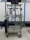
Anaesthetic machines vary between practices as some may be on trolleys while others may be mounted to the wall. However, they are all made up from the same basic components, which when understood make it possible to use any machine presented.
The basic components of a machine are: -
- Gas supply
- Pressure gauge
- Pressure reducing valves
- Flowmeters
- Vapourisers
- Common gas outlet
- Breathing system
Gas supply
A supply of gas to an anaesthetic machine can be either from cylinders or a piped source. Gases that are commonly used are oxygen, medical air and nitrous oxide.
Cylinders
Medical air and oxygen are both stored as compressed gases in cylinders, while nitrous oxide is stored as a liquid.
Identification
Cylinders are identifiable via a label around its neck as well as engraved details on the side of the valve block. There is also a colour code to prevent accidental misuse of a gas. In the UK the colour code is as follows -
- Oxygen - Black with a white shoulder.
- Nitrous Oxide - Blue
- Carbon Dioxide - Grey
Storage
Cylinders should be stored undercover, in a dry and clean ventilated area with no extremes of temperature. Full and empty cylinders should be kept separate and cylinders should be rotated such that the earliest date cylinder should be used first.
Pin Index
The pin index system valves can be found on the small cylinders which are frequently used on anaesthetic machines. It is designed to help prevent the incorrect attachment of cylinders on the anaesthetic machine.
Pipeline
Sources of pipeline gas supply include cylinder manifold, liquid oxygen storage tank or oxygen concentrators.
Cylinder Manifold
- Commonly found in larger veterinary hospitals for both oxygen and nitrous oxide.
- There is a pressure sensitive device that detects when the cylinders are nearly empty allowing automatic switch over from 'duty' to 'standby' cylinders, as well as sounding an alarm.
- Only trained staff should be allowed to change the cylinders and a logbook kept.
- Total capacity of the bank should be based on 1 week's supply of gas, with a minimum of 2 days' supply on each bank and 3 days on spare cylinders.
Liquid Oxygen Storage
- This is used when the annual consumption of oxygen by a veterinary hospital is too great for a cylinder manifold.
- Advantages include no need for manual handling and connection of cylinders, pressure regulator present and a safety valve to allow gas escape during periods of low demand.
Oxygen Concentrators
- Device which extracts oxygen from the air via chemical means, electrically powered.
Pressure Gauge
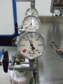
Pressure gauges indicate the pressure of gas in the pipeline of cylinders. Depending on the age of the machine they may be found above the cylinder yoke, or on the front panel of the machine. They are colour-coded and calibrated for each gas/vapour. While this oxygen gauge measures the pressure within the cylinder, which is directly related to the contents of the cylinder, the nitrous oxide gauge measures the saturated vapour pressure of the gaseous nitrous oxide and so does not indicate the fullness of the cylinder, and will only start to show a drop in pressure as the liquid nitrous is running low.
Pressure Reducing Valves
Pressure reducing valves (or pressure regulators) are used to reduce the pressures of the gases being delivered from the cylinder as well as maintaining a constant reduced pressure as the cylinder starts to run low. Machines using cylinders have a reducing valve for each cylinder while pipeline supplies have a regulator at the source. Pressure relief valves are found downstream allowing the escape of gas if the reducing valve is to fail. The final pressure reduction is carried about by control valves which regulate gas flow into the flowmeters via manual adjustment.
Flowmeters
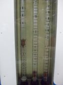
Flowmeters are made up of a transparent tube with either a bobbin or ball, which float in the gas flow. The flow rate is marked on the tubing, and the gas flows around the bobbin or ball, where if the flow increases then the marker will rise indicating a higher flow rate. If a bobbin is present then the flow rate is read from the top of the bobbin whereas if a ball is present then the flow rate is read from the line of the equator. Again, flowmeters are often colour coded for the gas that they are controlling, with oxygen commonly being white, while nitrous oxide is blue.
Flowmeters are supported along with the vapourisers and some other components on the backbar of anaesthetic machines.
Common Gas Outlet
The common gas outlet is where the breathing system is connected to the anaesthetic machine. It is also where a ventilator may be attached here. It can be either fixed or swivelled.
Oxygen Flush
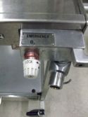
The emergency oxygen flush receives oxygen directly from the oxygen source and thereby bypassing the vapouriser. It delivers oxygen at a high flowrate and so care should be taken when used e.g. should never be used when connected to a patient.
Oxygen Failure Alarm
This alarm sounds when oxygen pressures fall, e.g. when a cylinder is empty indicating it's need to be changed over. It should ideally also prevent nitrous oxide delivery also if being used.
Checking an Anaesthetic Machine for Use
Before any anaesthetic machine is used it should be checked to make sure that all components are working correctly.
- Make sure that all cylinders are off and pressure gauges are reading red.
- If the machine is using cylinders for gas supply, then use the appropriate ratchet key to turn the cylinder on ('On' facing upwards) and check the pressure of that cylinder.
- Check the oxygen flush and flowmeters, checking that the bobbin/ball move up and down smoothly and does not get stuck.
- Turn off the cylinder and recheck the flowmeters - At this point the bobbin/ball may rise but then should fall as the gas still present in the system is flushed out.
- This process should be repeated for each of the cylinders.
- Turn on the 'In use' cylinder.
- Check the vapouriser is fitted correctly, the dial moves freely (make sure the gas flowmeter is turned off), and check the fluid level on the front of the vapouriser and fill if required.
- Check the breathing system for leaks etc.


